What matters most
- Molded-in inserts integrate installation with molding but require reliable insert location and retention in the tool.
- Heat-set and ultrasonic installation separate molding from assembly and can simplify tool construction.
- Boss geometry, resin behavior, insert design, and the required torque or pull-out test should be reviewed together.
Choose the installation route around the joint
Start with the functional load and service requirement, then compare tooling complexity, secondary equipment, inspection access, and production demand.
Joint load
Define clamp load, torque, pull-out, side load, and the number of assembly cycles.
Boss design
Review wall sections, knit lines, draft, radii, and distance from nearby edges.
Insert control
Specify orientation, location, contamination control, and the method used to detect a missing insert.
Validation
Agree on sample size, destructive testing, visual criteria, and traceability before approval.
Technical guide
The sections below retain the detailed design, tooling, process, and quality context needed to evaluate this topic beyond the summary.
When a plastic part needs a strong, reusable threaded connection — one that survives repeated assembly and disassembly without stripping — a molded-in plastic thread rarely cuts it. The answer is a metal threaded insert. But there are three very different ways to install one, and the right choice depends on your production volume, load requirements, and part material. This guide compares them and covers the boss design that makes any of them work.
Why threaded inserts
Self-tapping screws and molded plastic threads both wear out — every insertion shaves material, and after a handful of cycles the thread strips. A brass (or stainless) threaded insert puts durable metal threads into the plastic, giving:
- High pull-out and torque strength that plastic threads can't match.
- Repeated assembly without wear — critical for serviceable products.
- Consistent clamp load for structural or sealed joints.
The three installation methods
1. Molded-in inserts
The insert is loaded into the mold cavity before injection, and plastic flows around its knurls and undercuts under full pressure. This is a form of insert molding.
- Strongest pull-out and torque — the plastic keys into the insert with no residual stress.
- Downside: it slows the cycle (an operator or robot must load each insert), risks flash and mispositioning, and complicates the tool.
- Best for: high-load parts and thermosets, where maximum strength justifies the slower cycle.
2. Heat-set (thermal) inserts
After molding, a temperature-controlled tip heats the insert and presses it into a pre-molded hole; the surrounding plastic melts, flows into the knurls, and re-solidifies.
- Excellent strength — nearly molded-in performance without loading inserts in the tool.
- Flexible and forgiving: done as a fast secondary operation, easy to automate, low reject rate.
- Best for: most thermoplastic production — the default balance of strength, cost, and throughput.
3. Ultrasonic inserts
An ultrasonic horn vibrates the insert at high frequency; friction melts the plastic locally and the insert seats in a second or two.
- Fast and repeatable — ideal for high-volume automated lines.
- Strength comparable to heat-set when the horn and hole are tuned.
- Best for: high-volume thermoplastic parts where cycle time dominates cost.
Quick comparison
- Strength: molded-in > heat-set ≈ ultrasonic > press-fit.
- Cycle impact: molded-in slows the press; heat-set and ultrasonic are fast post-mold steps.
- Volume fit: ultrasonic and heat-set scale best; molded-in suits lower volumes or highest loads.
- Tooling risk: molded-in adds tool complexity; the post-mold methods keep the tool simple.
Boss design — where inserts succeed or crack
No installation method saves a bad boss. Get these right:
- Boss OD ≈ 2× insert OD. Too thin and hoop stress cracks the boss; too thick and you get sink marks.
- Hole diameter per the insert spec. Heat-set and ultrasonic want a slight interference so melted plastic fills the knurls; molded-in wants a clean locating fit.
- Lead-in chamfer to start the insert straight and give displaced plastic somewhere to go.
- Adequate depth below the insert so it can't blow through a thin floor.
Settle it in DFM
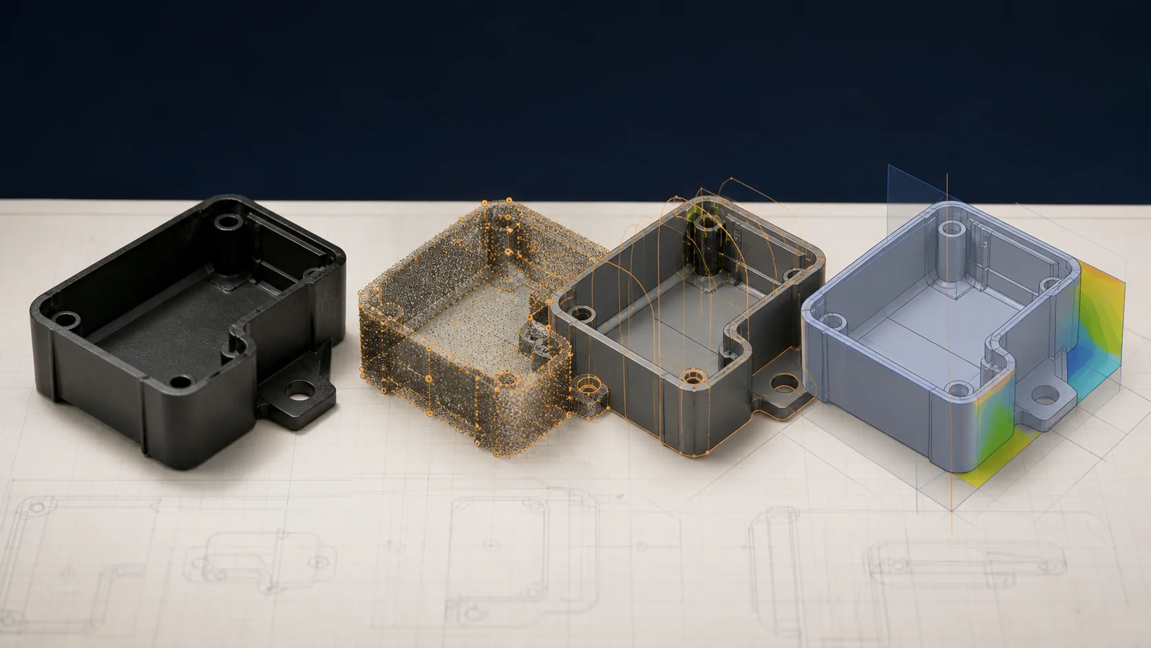
Insert type, boss dimensions, and hole geometry all interact with the resin and the mold layout — so decide them during the mold design and tooling review, not after tooling. If your part needs metal threads, our team can recommend the method and boss design for your material and volume as part of an initial engineering review — send us the drawing and we will spec it before the mold is cut.
What to confirm before supplier review
Use the drawing, material specification, expected demand, application conditions, and acceptance requirements to turn a general process discussion into a program-specific review.
- Which installation method is being quoted, and why does it fit the expected demand?
- How will insert presence, position, and orientation be verified?
- Which torque and pull-out requirements appear on the drawing or test specification?
- How will the supplier prevent damage to threads during molding and handling?
Continue the engineering review
Use the related guides and capability pages to connect this topic to part geometry, tooling, molding, and qualification decisions.