What matters most
- Record cycle stages, process settings, cavity behavior, part temperature, quality results, scrap, and handling.
- Review wall sections, material, ribs, cores, gates, and ejection features that control cooling or release.
- Evaluate cooling balance, water flow, vents, runner, actions, maintenance, and sensor needs.
Optimize the constraint, then verify the part
Evaluate the technical choice together with part requirements, tooling consequences, production controls, and the evidence required for approval.
Baseline
Record cycle stages, process settings, cavity behavior, part temperature, quality results, scrap, and handling.
Part design
Review wall sections, material, ribs, cores, gates, and ejection features that control cooling or release.
Tooling
Evaluate cooling balance, water flow, vents, runner, actions, maintenance, and sensor needs.
Verification
Confirm dimensions, appearance, function, process stability, and economics over a representative run.
Technical guide
The sections below retain the detailed design, tooling, process, and quality context needed to evaluate this topic beyond the summary.
Key Takeaways
- 1 Cooling time accounts for 60–80% of total injection molding cycle time — making it the single largest lever for reducing piece price at volume.
- 2 Conformal cooling channels deliver 20–40% cooling time reduction versus conventional straight-line channels; at 100,000 parts per year with a machine rate of $120/hr, cutting a 40-second cycle to 32 seconds saves approximately $27,000/year in machine time alone.
- 3 Five engineering levers determine cycle time: wall thickness design, cooling channel geometry, runner system, in-mold process monitoring, and machine type — each with a distinct investment profile and payback period.
- 4 All-electric injection molding machines achieve 30–50% faster dry-cycle times than hydraulic systems and consume 50–70% less energy — compressing cycle time while lowering operating cost per part.
Cycle time is the single number that connects tooling engineering to production economics. A 60-second cycle time costs exactly twice as much in machine overhead as a 30-second cycle on the same press — and for programs running 100,000 to 500,000 parts per year, a 20% cycle time reduction translates directly to tens of thousands of dollars in annual savings without touching part design or material cost. This guide covers the five engineering levers that injection molding engineers and procurement teams can pull to reduce cycle time, ranked by typical impact and investment required.
The Cycle Time Equation: Where Production Time Is Actually Spent
Total injection molding cycle time is the sum of four sequential phases, as formalized in the 2026 Engineering Cycle Time Guide from TEDE Solutions:
Of these four phases, cooling time (t_cool) dominates the total. Silkbridge’s cycle time analysis reports that cooling accounts for 60–80% of total cycle duration in most production programs, because plastic must solidify to a safe ejection temperature before the mold can open. The remaining 20–40% is split among injection, packing, and mold open/close mechanics. This distribution explains why wall thickness and cooling channel design deliver the largest cycle time returns per engineering dollar invested, and why process monitoring and machine type play secondary but meaningful roles.
| Cycle Phase | What Controls It | Typical Share of Cycle | Primary Optimization Lever |
|---|---|---|---|
| Injection (t_fill) | Injection speed, resin viscosity, gate size | 3–8% | Gate design, injection speed, resin grade |
| Packing / Holding (t_pack) | Hold pressure, gate freeze time, wall thickness | 8–15% | Scientific molding; optimized hold pressure profile |
| Cooling (t_cool) | Wall thickness, resin thermal diffusivity, coolant temperature and flow rate | 60–80% | Wall thickness reduction; conformal cooling channels |
| Mold Open / Eject (t_open_eject) | Machine dry-cycle speed, ejection stroke, robot extraction | 5–15% | All-electric press; automation |
Levers 1 and 2: Wall Thickness Design and Conformal Cooling Channels
Lever 1 — Wall thickness optimization is the highest-impact DFM decision because cooling time scales with the square of wall thickness. Reducing a 3.0 mm wall to 2.0 mm cuts theoretical cooling time by approximately 56% — a gain that no tooling modification after mold cut can replicate. This lever is available only at the design stage, which is precisely why DFM review before tooling kick-off is the most cost-effective cycle time intervention: it costs zero in tooling and delivers results that persist for the life of the program.
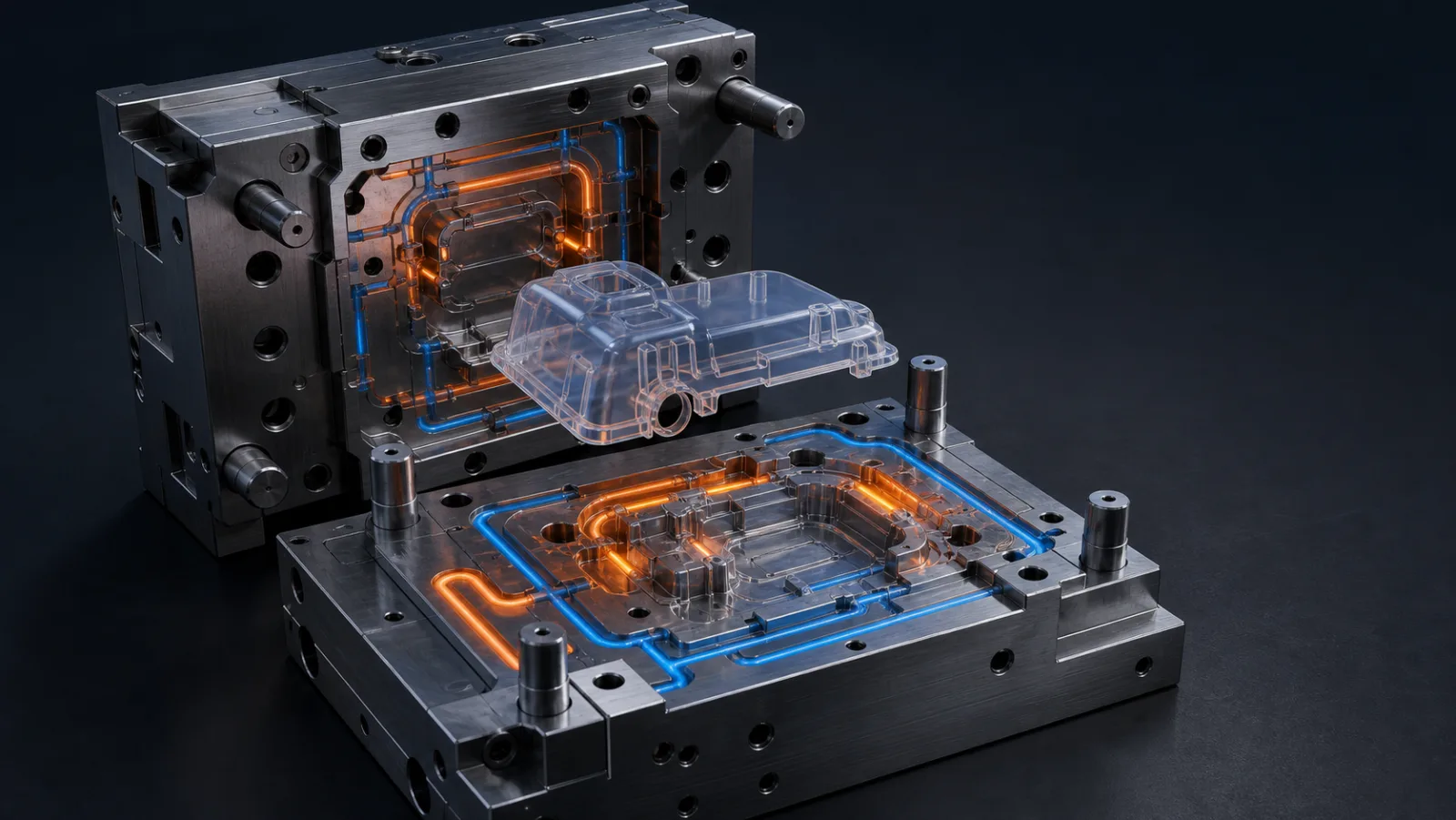
Lever 2 — Conformal cooling channels are the most powerful tooling-side intervention. Conventional straight-line water channels maintain a fixed distance from the cavity surface; conformal channels manufactured via selective laser melting (SLM) follow the cavity contour precisely, delivering uniform heat extraction at every point across the part surface. Xometry’s conformal cooling guide documents 20–40% cooling time reductions in production programs, and a 2025 peer-reviewed review in Computer-Aided Design (ScienceDirect) confirmed cooling cycle reductions exceeding 30% in complex cavity geometries where conventional channels cannot maintain uniform temperature.

The ROI math for conformal cooling is direct. At 100,000 annual parts with a machine rate of $120/hr, a 40-second cycle generates $333 in machine overhead per 100 parts. Reducing that cycle to 32 seconds — a 20% reduction achievable with conformal cooling on a typical consumer electronics enclosure or automotive trim component — saves approximately $27,000 per year at 100,000 volume. RapidDirect’s 2026 cost breakdown confirms the principle: a 60-second cycle costs exactly twice as much in machine overhead as a 30-second cycle. Conformal SLM inserts for a mid-size mold typically cost $8,000–$20,000, delivering payback within 12 months on a 100,000-part program and under 3 months for programs above 500,000 parts per year.
Levers 3 and 4: Hot Runner Systems and In-Mold Process Monitoring
Lever 3 — Hot runner systems eliminate the cold runner from the cycle equation. In a cold runner mold, the material in the runner network must freeze and be ejected with every cycle — adding runner cooling time, degating labor, and regrind material handling. A hot runner system maintains the runner manifold at melt temperature throughout the cycle, removing runner freeze as a cycle constraint and enabling faster, cleaner cycles particularly in multi-cavity tools where runner volume is proportionally large. This is especially impactful for engineering resins such as PA66 and PC, where runner volumes are substantial and regrind reprocessing introduces property variability.
Lever 4 — In-mold process monitoring with cavity pressure and temperature sensors — systems such as RJG eDART and Kistler CoMo — provides the data foundation for systematic cycle time optimization. Without sensor feedback, engineers set conservative packing and cooling times to prevent short shots and sink marks, accepting a margin of safety that routinely adds 3–10 seconds of unnecessary cycle time per shot. With real-time cavity pressure curves, the exact gate freeze point is visible, packing time is set to the minimum required to achieve dimensional stability, and cooling time is held to the minimum consistent with safe ejection temperature. Both RJG and Kistler document consistent 5–10% cycle reductions at first implementation on molds where process parameters were previously set by convention rather than measured data — with zero tooling investment required.
Lever 5: All-Electric Injection Machines and the Full ROI Picture
Lever 5 — All-electric injection molding machines contribute cycle time reduction primarily through the mold open/eject phase, which conventional hydraulic machines execute comparatively slowly due to hydraulic response lag and oil circuit inertia. Servo-electric drives respond with faster acceleration and tighter deceleration control, translating to 30–50% faster dry-cycle times on comparable tonnage. TopStar Machine’s efficiency comparison confirms all-electric machines consume 50–70% less energy than hydraulic equivalents; TEDE Solutions’ 2026 engineering guide documents opening and closing times 30–50% faster than hydraulic presses at comparable tonnage. For high-cadence multi-cavity tools where mold open/eject represents 15% of total cycle, a 40% improvement in that phase yields a net 6% total cycle reduction with no tooling changes — alongside the energy cost reduction that further lowers operating cost per part.
The table below synthesizes all five levers with typical performance ranges, investment requirements, and program fit, based on data from Silkbridge, TEDE Solutions, and Xometry:
| Optimization Lever | Typical Cycle Time Saving | Investment Level | Best For |
|---|---|---|---|
| 1. Wall Thickness Reduction | 15–50% (depends on thickness delta) | None (design change only) | New programs at DFM stage; not available post-tooling |
| 2. Conformal Cooling Channels | 20–40% cooling time reduction | Medium–High ($8K–20K per SLM insert) | High-volume parts >50,000/year with complex geometry |
| 3. Hot Runner System | 5–15% (removes runner freeze) | Medium ($3K–15K hot runner system) | Multi-cavity molds; engineering resins; high-cosmetic parts |
| 4. In-Mold Process Monitoring | 3–10% (removes conservative time margin) | Medium ($5K–25K sensor package) | Scientific molding programs; IATF 16949 automotive programs |
| 5. All-Electric Press | 6–15% total cycle (via faster open/close) | High (machine CapEx, offset by 50–70% energy savings) | New press investment; precision thin-wall; cleanroom programs |
Request a Cycle Time and Piece-Price Analysis from LongTeam
LongTeam’s engineering team reviews part geometry, wall thickness, and cooling channel layout to identify the highest-impact cycle time levers for your program — before tooling begins. LongTeam connects tooling and molding input when evaluating cycle-time levers. Scientific-molding methods, monitoring needs, and conformal-cooling analysis are scoped to the specific program. Share your part drawing and annual volume target to receive a cycle time estimate and piece-price analysis.
Get a Cycle Time and Piece-Price Analysis →What to confirm before supplier review
Use the drawing, material specification, expected demand, application conditions, and acceptance requirements to turn a general process discussion into a program-specific review.
- Which stage currently limits the cycle?
- What evidence shows the proposed root cause?
- Which quality result could worsen when time is removed?
- How will the revised process be approved and controlled?
Continue the engineering review
Use the related guides and capability pages to connect this topic to part geometry, tooling, molding, and qualification decisions.