What matters most
- Review flow length, thickness transitions, air traps, weld lines, and pressure demand.
- Define whether the gate mark is visible and what finishing is acceptable.
- Consider how the gate supports packing of thick or dimensionally important regions.
Place the gate around function and flow
Evaluate the technical choice together with part requirements, tooling consequences, production controls, and the evidence required for approval.
Fill path
Review flow length, thickness transitions, air traps, weld lines, and pressure demand.
Appearance
Define whether the gate mark is visible and what finishing is acceptable.
Packing
Consider how the gate supports packing of thick or dimensionally important regions.
Production
Include degating, automation, maintenance, cavity count, and runner strategy in the choice.
Technical guide
The sections below retain the detailed design, tooling, process, and quality context needed to evaluate this topic beyond the summary.
Key Takeaways
- 1 Gate type and location is one of the highest-impact mold design decisions — wrong gate placement causes sink marks, weld lines, warpage, and cosmetic rejects that cost 3–10× more to fix after T0 than before tooling approval.
- 2 Six gate types cover the vast majority of injection molded parts: edge, submarine (tunnel), pin, fan, valve, and diaphragm/ring — each with distinct trade-offs on vestige size, auto-degating, material compatibility, and tooling cost.
- 3 Glass-filled resins (PA66-GF30, PP-GF20) must avoid submarine gates — fiber reinforcement fractures during auto-shear ejection; use H13 hardened steel edge gates or hot-runner valve gates for filled materials instead.
- 4 At 500,000 annual shots, eliminating just 2 seconds of manual gate trimming per part saves roughly 278 machine-hours per year — the economic break-even case for upgrading to auto-degating submarine or valve gate systems at volume.
What Is an Injection Molding Gate — and Why Does It Matter?
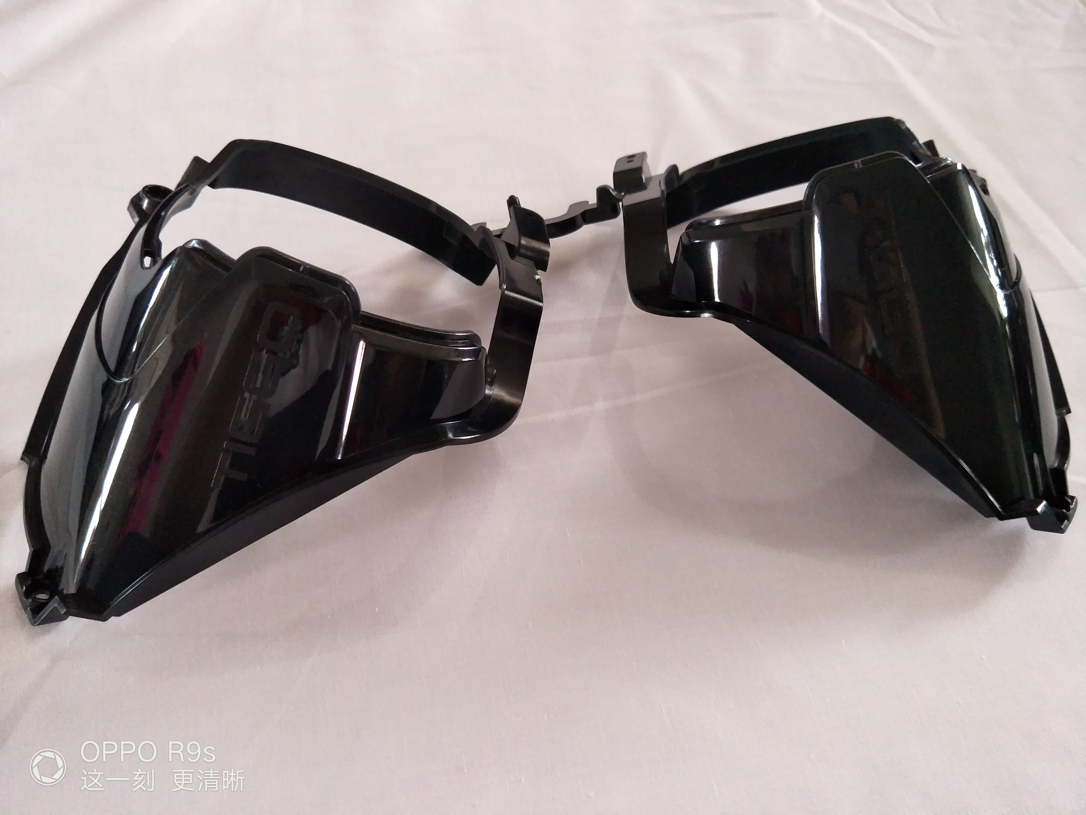
The gate is the controlled opening through which molten plastic flows from the runner system into the mold cavity. At typical injection pressures of 10,000–30,000 psi, the gate restricts flow to build back-pressure that packs the cavity uniformly — and then freezes first after fill, sealing the cavity before the part solidifies. Once the part ejects, the gate leaves a vestige: a small mark or protrusion at the entry point whose size, location, and appearance depend entirely on gate geometry.
Gate design is a critical DFM decision because it directly determines four key outcomes: weld line location (where two melt fronts meet and fuse, creating a potential weak point), warpage (asymmetric fill patterns create asymmetric residual stress), surface cosmetics (vestige location and size drive post-mold finishing cost), and cycle time (gate freeze time sets the minimum hold time). Fictiv’s injection molding design guide notes that gate placement determines where weld lines, sink marks, and voids occur — and relocating a gate after tooling is complete typically requires re-machining the cavity steel or inserting a gate plug, costing $500–$5,000 and delaying production by weeks.
Gate design is therefore a DFM-stage decision, not a tooling detail. Engineers and product designers who understand gate geometry before T0 can specify gate type, location, and size during the DFM review — avoiding the expensive corrections that come from discovering gate-related defects during mold trials.
The Six Primary Gate Types: Characteristics and Selection Logic
1. Edge Gate (Side Gate)
The most common gate type, positioned on the parting line along the part edge. Typical dimensions: width 0.5–5 mm, thickness 0.2–2 mm, land length 0.5–2 mm. Sussex IM’s gate design guide identifies edge gates as the standard starting choice for general-purpose parts: low tooling cost, easy field adjustment (file the steel wider to reduce shear; add a gate insert to reduce size if flow marks appear), and compatible with nearly all thermoplastics. Primary limitation: a visible vestige (0.5–2 mm square mark) on the part edge requires manual or automated runner removal at each cycle.
2. Submarine Gate (Tunnel Gate)
The submarine gate enters the part below the parting line through a curved tunnel machined into the ejector half. During ejection, the gate automatically shears, separating the part from the runner without operator intervention. ZetarMold’s gate type analysis documents vestige below 0.1 mm on clean-shearing resins — nearly invisible on production parts. Ideal for ABS, PP, HIPS, and unfilled nylons at high volume (100,000+ shots/year). Critical limitation: glass- or mineral-filled resins cannot use submarine gates. Fiber reinforcement resists shear and causes gate tip fracture at ejection, generating breakage failures and mold damage. Use H13 hardened steel edge gates or valve gates for all filled grades.
3. Fan Gate
The fan gate spreads flow across a wide, thin entry that reduces shear stress and improves fill distribution across flat, thin-walled, or optically clear parts. According to VEM Tooling’s gate resource, fan gates are the preferred choice for PC, PMMA (acrylic), and other brittle or transparent materials where shear-induced stress whitening or jetting would compromise optical clarity or impact resistance. The trade-off is a wide vestige requiring manual trimming, typically located on a B-surface or recessed edge.
4. Pin Gate (Three-Plate Mold)
A small-diameter gate (0.5–2 mm) that enters the part from the top face via a three-plate mold with a dedicated runner plate. The runner and gate separate automatically when the mold opens at the runner plate parting line. Pin gates allow center-top gating on round, symmetric, or hub-shaped parts where an edge gate would create asymmetric fill and warpage. The three-plate tool adds 15–25% to mold cost versus a standard two-plate design but enables balanced multi-point gating on complex geometries without a hot runner investment.
5. Valve Gate (Hot Runner)
A pneumatically or servo-driven pin closes the gate precisely at pack completion, leaving a vestige under 0.1 mm — a flat circular mark equal to the pin diameter that is often acceptable on visible A-surfaces. ZetarMold’s tooling cost data puts the premium at $1,500–$3,500 per valve drop versus a standard hot tip, but valve gates eliminate runners entirely (saving resin at every shot), deliver the best cosmetic result of any gate type, and allow independent sequencing of open/close times in multi-gate sequential filling programs. For automotive Class-A interior surfaces and medical visible components, valve gates are the industry standard.
6. Diaphragm Gate (Ring Gate)
For cylindrical, tubular, or hub-shaped parts where concentricity and elimination of weld lines are essential, the diaphragm gate fills the entire perimeter simultaneously. A full-perimeter vestige is trimmed in a secondary die-cutting or turning operation — adding labor cost but producing a part with no weld lines and minimal hoop-stress concentrations. Common applications include precision bushings, optical lens holders, and medical tubular components where a single weld line would represent a structural or sealing failure point.
Gate Type Quick-Reference Comparison
The table below consolidates selection criteria across the six primary gate types. Data compiled from ZetarMold, Sussex IM, and SEAWIN Industrial.
| Gate Type | Vestige Size | Auto-Degateable | Best Material Match | Tooling Cost |
|---|---|---|---|---|
| Edge (Side) | 0.5–2 mm square | No (manual/auto cut) | All thermoplastics | Low |
| Submarine (Tunnel) | <0.1 mm | Yes (shears at ejection) | ABS, PP, HIPS, unfilled PA | Low–Medium |
| Fan | Wide edge vestige | No (manual trim) | PC, PMMA, brittle/clear resins | Low–Medium |
| Pin (3-plate) | <0.5 mm | Yes (runner plate opens) | General purpose, multi-cavity | Medium (+15–25%) |
| Valve Gate (hot runner) | <0.1 mm flat mark | N/A (no runner) | All; ideal for filled & cosmetic | High (+$1,500–$3,500/drop) |
| Diaphragm (Ring) | Full perimeter | No (secondary op) | Cylindrical/tubular parts | Medium |
Five Gate Location Design Rules That Prevent Costly Rework
-
1
Gate at the thickest wall section. Plastic flows from thick to thin, not the reverse. Gating at a thin section forces the melt to push through a restriction before filling the thick region, causing premature freeze-off, short shots, and excessive packing pressure. Fictiv’s DFM guide identifies this as the most common gate location error on designer-submitted parts.
-
2
Push weld lines away from structural features. Where two melt fronts converge, molecular entanglement is reduced, leaving a weld line at 50–90% of parent material strength in glass-filled grades. Use mold flow simulation before cutting steel to predict weld line location — then shift the gate or add a second gate point to relocate weld lines away from screw bosses, snap-fit arms, and load-bearing ribs. SEAWIN Industrial’s gate analysis demonstrates that multi-point gating is the most reliable method for moving weld lines into non-critical zones.
-
3
Place vestige on a hidden (B-surface) face. Even a well-trimmed edge gate leaves a witness mark. Unless a valve gate is specified, gate location should be on the non-cosmetic face, in a recessed pocket, or on the parting line edge where it will be mated or covered in assembly. Critical mating surfaces and Class-A cosmetic faces must be excluded from gate location consideration at the DFM stage.
-
4
Minimize the flow length-to-wall-thickness ratio. Every additional millimeter of flow path requires higher injection pressure to overcome viscous resistance. Long fill paths increase shear heating (degrading thermally sensitive materials like POM and PVC), raise the risk of incomplete fill on thin walls, and amplify residual stress at end-of-fill. Most resins perform reliably below a flow length-to-wall-thickness (L/T) ratio of 100:1; gate placement should minimize the maximum L/T across all part features.
-
5
Match gate size to resin viscosity and verify with a gate freeze study. A gate too small generates excessive shear stress that degrades the polymer and produces burn marks near the gate; too large delays gate freeze, extending cycle time and enabling sink marks from over-packing. Standard edge gate dimensions run 0.5–5 mm wide by 0.2–2 mm thick, with ±0.02 mm dimensional tolerance on normal tooling. Verify gate freeze by incrementally increasing hold time until part weight stabilizes — the minimum hold time where weight no longer increases is the gate freeze point, and it sets the production hold time floor.
Get a Gate Type Recommendation in Your DFM Review
LongTeam’s DFM review process includes gate type selection, gate location analysis, and mold flow guidance before tooling approval — addressing decisions that cost pennies to change at the design stage and thousands to fix after T0. Founded in 1989, LongTeam brings integrated tooling and molding experience to gate, runner, and weld-line decisions. The required DFM deliverables are confirmed before tooling approval.
Contact LongTeam for a DFM Gate ReviewWhat to confirm before supplier review
Use the drawing, material specification, expected demand, application conditions, and acceptance requirements to turn a general process discussion into a program-specific review.
- Where may a gate vestige appear?
- Which weld-line locations are functionally sensitive?
- How will the gate be removed or separated?
- Has the proposed gate been reviewed with the runner and cooling layout?
Continue the engineering review
Use the related guides and capability pages to connect this topic to part geometry, tooling, molding, and qualification decisions.