What matters most
- Mark the undercut, pull direction, required travel, shutoff length, draft, and acceptable witness lines.
- Compare slide, lifter, hand-loaded insert, collapsible core, unscrewing, and part redesign.
- Review locking, guidance, cooling, ejection sequence, sensors, interference, and steel strength.
Resolve undercuts with the simplest reliable release strategy
Evaluate the technical choice together with part requirements, tooling consequences, production controls, and the evidence required for approval.
Geometry
Mark the undercut, pull direction, required travel, shutoff length, draft, and acceptable witness lines.
Mechanism
Compare slide, lifter, hand-loaded insert, collapsible core, unscrewing, and part redesign.
Tool integration
Review locking, guidance, cooling, ejection sequence, sensors, interference, and steel strength.
Lifecycle
Plan lubrication, wear surfaces, access, replacement, inspection, and failure detection.
Technical guide
The sections below retain the detailed design, tooling, process, and quality context needed to evaluate this topic beyond the summary.
Key Takeaways
- 1 Any feature that casts a shadow when light shines in the mold pull direction is an undercut — it requires either a side action or a design modification to eject cleanly.
- 2 Each slider adds $4,000–$10,000 in tooling cost (Chinese tooling) and 2–4 weeks to mold fabrication; a lifter adds $1,500–$4,000 per action.
- 3 The right mechanism depends on where the undercut sits: sliders handle external features; lifters handle internal ones; collapsible cores tackle internal threads and deep circular undercuts.
- 4 A DFM review before tooling confirmation can identify eliminations that save 20–40% of side-action tooling cost — often by reorienting a feature, adding a through-slot, or switching to a post-mold insert.
Injection molds open and close in a straight line. Every feature that blocks that motion — a side hole, a snap hook, an internal thread, a groove on the outer wall — is an undercut. Undercuts are not a design failure; many functional products genuinely require them. But understanding which type of side action to use, what it costs, and whether the undercut can be eliminated is one of the highest-leverage DFM skills in injection molding.
What Is an Undercut — and Why Does It Require a Side Action?
An undercut is any geometry that would prevent a molded part from being ejected along the mold’s primary opening axis. The classic field check is the shadow rule: hold a light source in line with the pull direction. If any feature casts a shadow on the cavity or core below it, that feature is an undercut requiring action or redesign.
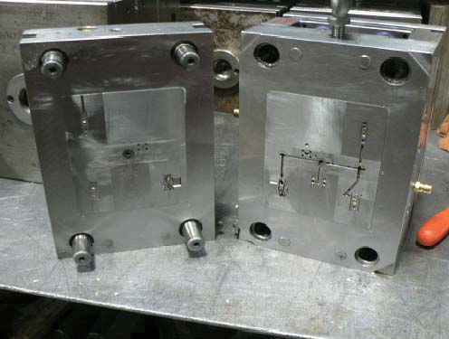
Common undercut-generating features include: side holes or ports perpendicular to the pull direction; exterior hooks, clips, and snap fingers; interior snap-arms; threaded holes parallel to the parting line; grooves or channels on the outer wall; and recessed lettering on side walls. Each requires a mechanical side action inside the mold to form the feature and retract before the part ejects.
According to Xometry’s side actions guide, adding side actions can increase tooling cost by 15–40% depending on the number and complexity of the mechanisms required. A DFM review before the mold design is finalized can eliminate a significant portion of that premium.
The Four Main Side Action Types — Compared
Choosing the right mechanism depends on undercut location (external vs. internal), geometry (linear, angular, or circular), and production volume. The table below summarizes the four principal options based on Fictiv’s molding guide and Zetar Mold’s 2026 pricing data:
| Type | Undercut Location | Typical Application | Cost Range (China Tooling) | Cost Range (Western Tooling) | Key Risk |
|---|---|---|---|---|---|
| Slider (Slide) | External | Side holes, exterior clips, ports, grooves on outer wall | $4,000–$10,000 per action | $8,000–$20,000 per action | Cam wear; flash at parting line if slide pressure drops |
| Lifter | Internal | Interior snap-fits, ribs on inner walls, internal hooks | $1,500–$4,000 per lifter | $3,000–$8,000 per lifter | Sticking if draft is insufficient; limited stroke on deep features |
| Collapsible Core | Internal (circular) | Internal threads, bottle necks, deep circular undercuts | $10,000–$30,000 | $20,000–$50,000 | Most complex mechanism; maintenance-intensive; max ~150 mm diameter |
| Unscrewing / Rotating Core | External or internal | External threads, bottle caps, helical features | $5,000–$15,000 | $10,000–$25,000 | Cycle time penalty: motor rotation adds 3–10 sec per cycle |
A mold with two sliders typically runs 3–8 seconds slower per cycle than an equivalent straight-pull mold. At 100,000 parts per year, that represents 83–222 additional machine-hours annually — a hidden operating cost that should factor into the keep-vs.-redesign decision alongside tooling cost.
Five DFM Strategies to Minimize or Eliminate Undercuts
The most effective time to eliminate a side action is before the mold design starts. Here are five strategies used in DFM reviews at experienced molders:
1. Reorient the part in the mold. A side hole perpendicular to the current pull direction may align with the pull direction if the part is rotated 90° in the mold. Always evaluate whether the parting line and pull direction are fixed or can be optimized for the full feature set before locking the tool layout.
2. Add a through-slot behind a snap hook. Snap hooks create undercuts perpendicular to the pull axis. Adding a through-slot directly behind the snap arm allows mold steel to pass cleanly through, eliminating the lifter while preserving snap functionality. Confirm the slot is acceptable in the end-use environment.
3. Convert exterior grooves to exterior ribs. A groove around the outside of a part creates a 360° external undercut requiring a split slide. An equivalent outward-raised rib delivers similar aesthetics and grip without any undercut, eliminating the mechanism entirely.
4. Replace internal threads with post-mold inserts. Internal threads drilled parallel to the parting line require unscrewing actions or collapsible cores costing $5,000–$30,000. Substituting a heat-staked or ultrasonic-welded threaded insert installed post-mold eliminates the mechanism. Total assembled cost is similar or lower for volumes under 50,000 units annually.
5. Use material deflection for shallow undercuts in flexible resins. For undercut depths of 0.5–2 mm on PP, PE, or TPE, the part can often be stripped off the core without mechanical action. The molder must confirm the strip ratio (undercut depth vs. wall thickness) and material elongation before approving this approach.
A thorough DFM review before tooling start can reduce side-action-related tooling costs by 20–40% by catching eliminations the designer did not know were possible — with no impact on part functionality or program schedule.
When Keeping the Undercut Is the Right Call
Not every undercut should be eliminated. The decision rests on three factors:
Functional necessity. Side-entry ports on fluid components, snap-fit assembly features, and grip grooves on handheld devices cannot always be relocated without compromising performance. When the undercut is genuinely functional, a well-engineered slider or lifter is the correct tooling solution.
Production volume. For volumes below 5,000 parts per year, a hand-loaded insert — a removable steel piece placed manually each cycle — often costs less over program life than a powered slide, because the lower tool cost outweighs added labor. Above 20,000 units annually, automated slides and lifters almost always win on total cost.
Design stability. If the design is still evolving, adding a complex side action locks in geometry that may change. Hand-loads or design modifications preserve engineering flexibility. Once steel is cut for a cam-driven slider, revising the undercut geometry typically costs $3,000–$8,000 for a new slide body — a strong reason to finalize design intent before tooling begins.
Get a Side-Action Review Before Your Mold Is Quoted
LongTeam’s engineering team can review submitted designs for undercuts and side-action requirements before tooling confirmation. We flag every side action, evaluate elimination options, and quote both the optimized and as-designed configurations so you can make an informed tooling investment decision. LongTeam evaluates side-action tooling against the program’s geometry, schedule, inspection, and process-control requirements before quotation.
Request an Engineering ReviewWhat to confirm before supplier review
Use the drawing, material specification, expected demand, application conditions, and acceptance requirements to turn a general process discussion into a program-specific review.
- Can the feature be redesigned for straight-pull molding?
- What travel and locking force does the action require?
- Where will witness lines or draft changes appear?
- How will action position and wear be monitored?
Continue the engineering review
Use the related guides and capability pages to connect this topic to part geometry, tooling, molding, and qualification decisions.