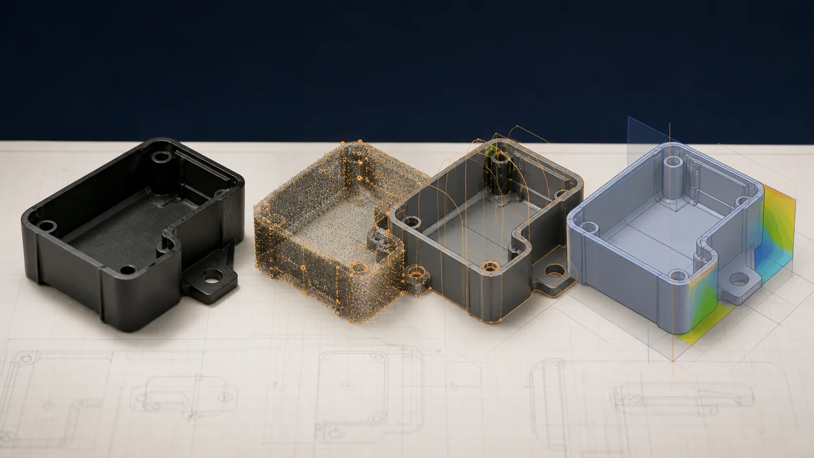
What matters most
- Review wall sections, transitions, ribs, bosses, radii, holes, undercuts, and assembly features.
- Define pull direction, parting line, gates, vents, cooling, side actions, ejection, and visible marks.
- Use the exact proposed grade when assessing shrinkage, flow, strength, appearance, and conditioning.
Resolve the design-to-tool interfaces
Evaluate the technical choice together with part requirements, tooling consequences, production controls, and the evidence required for approval.
Geometry
Review wall sections, transitions, ribs, bosses, radii, holes, undercuts, and assembly features.
Mold
Define pull direction, parting line, gates, vents, cooling, side actions, ejection, and visible marks.
Material
Use the exact proposed grade when assessing shrinkage, flow, strength, appearance, and conditioning.
Acceptance
Mark critical dimensions, datum strategy, cosmetic zones, tests, and required documentation.
Technical guide
The sections below retain the detailed design, tooling, process, and quality context needed to evaluate this topic beyond the summary.
Key Takeaways
- 1 DFM issues discovered after tooling cost 10× more to fix than those caught during design review — front-loading analysis is the single highest-ROI action in any mold program.
- 2 Wall thickness inconsistency, insufficient draft angles, over-sized ribs, and unaddressed undercuts account for the majority of first-tool-shot failures and mold rework costs.
- 3 Reducing average wall thickness by just 0.5 mm can cut injection cycle time by up to 20% — a direct reduction in per-unit cost at high production volumes.
- 4 LongTeam’s pre-tooling review considers part geometry, material choice, gate strategy, and tooling risks before steel is approved. The exact DFM scope is confirmed for each program.
What Is DFM — and Why Does It Matter Before Steel Is Cut?
Design for Manufacturability (DFM) is the structured review of a plastic part’s geometry, wall sections, and features against the physical constraints of the injection molding process — conducted before a mold is machined. The goal is to identify and resolve issues that would cause sink marks, warping, short shots, ejection damage, or weld-line failures at the lowest possible cost: a CAD change.
The economics are well established. According to analysis by TechNH and Entech Plastics, effective DFM can reduce total project costs by 10% to 50% compared to programs that proceed to tooling without systematic design review. That range widens when mold rework, delayed production launch, and first-article qualification scrap are included in the calculation.
For product engineers, DFM translates to a concrete checklist applied to every feature on every part. The sections below walk through the six parameters LongTeam’s engineers examine in every pre-tooling review, with the specific numbers that separate an acceptable design from a costly mold modification.
The 6 Critical DFM Parameters
1. Wall Thickness — Uniformity Over Absolute Value
Wall thickness is the most impactful single variable in injection molded part design. Thick sections cool slowly, creating sink marks and internal voids; abrupt transitions between thin and thick walls cause differential shrinkage and warping. The rule is to maintain all walls within ±25% of nominal thickness for amorphous resins (ABS, PC) and within ±15% for semi-crystalline resins (nylon, PP), where higher shrinkage rates amplify any inconsistency.
Recommended nominal wall thickness ranges vary by material. The table below reflects industry consensus values from Moldie and Protolabs:
| Material | Min Wall (mm) | Max Wall (mm) | Typical Nominal (mm) |
|---|---|---|---|
| ABS | 1.14 | 3.56 | 1.5 – 2.5 |
| Polycarbonate (PC) | 1.02 | 3.81 | 1.5 – 2.5 |
| Nylon (PA6 / PA66) | 0.76 | 2.92 | 1.0 – 2.0 |
| Polypropylene (PP) | 0.64 | 3.81 | 1.0 – 2.5 |
| Acetal (POM) | 0.76 | 3.05 | 1.2 – 2.5 |
| Polystyrene (PS) | 0.89 | 3.81 | 1.0 – 2.5 |
2. Draft Angles — Ejection Without Damage
Vertical walls with zero taper grip the mold as the part cools and contracts, causing drag marks, surface tearing, and ejector-pin deformation. Per Protolabs’ design guidelines, 1–2° per side is the baseline for most features, scaling up with cavity depth and surface texture:
- Polished Class A surfaces: 0.5° minimum per side
- Standard semi-gloss surfaces: 1.0° per side
- Light EDM or bead-blast texture (PM-T1): 3.0° per side
- Medium / heavy texture (PM-T2): 5.0° or more per side
- Mold shutoff surfaces: 3.0° minimum to form a reliable steel-to-steel seal
3. Ribs and Bosses — Stiffness Without Sink
Ribs add structural stiffness without increasing nominal wall thickness — but only when sized correctly. Oversized ribs create thick local sections that sink. Industry-standard rib geometry per Manufyn’s rib and boss design guide:
- Rib thickness: 50–60% of adjacent wall (40% for high-gloss surfaces)
- Rib height: less than 3× nominal wall thickness
- Rib spacing: 2–3× nominal wall minimum to allow gas venting and mold machining access
- Base fillet radius: 25% of rib thickness minimum to reduce stress concentration
Bosses follow the same 50–60% wall ratio; outside diameter should be 2.0–2.4× the screw or insert outer diameter, and height should stay below 3× the outside diameter to prevent fill and ejection problems.
4. Undercuts — Eliminate or Justify
An undercut is any feature that prevents straight-pull ejection: side holes, external hooks, internal threads, and snap-fit ledges all qualify. Each requires a mechanical side action (lifter or cam) in the mold. Adding a single side action typically increases tooling cost by $5,000–$10,000 per action and extends the mold build timeline. Where undercuts cannot be eliminated through geometry redesign, LongTeam evaluates collapsible cores, hand-loaded inserts, or parting-line shifts as lower-cost alternatives.
5. Gate Location and Type
Gate position determines fill direction, weld-line placement, and visible gate vestiges. Gates should be placed at the thickest wall section to ensure complete fill before the flow front reaches thin areas. Weld lines — where two flow fronts meet — are inherently weaker than the surrounding material and should be directed away from structural or cosmetic surfaces through gate positioning, not removed after the mold is built.
6. Radii and Sharp Corners
Sharp internal corners are stress risers in both the molded part and the mold steel itself. A minimum internal radius of 0.5× the adjacent wall thickness distributes stress and improves material flow through the feature. Sharp external corners on the mold concentrate EDM and machining stress and tend to chip during hardening — a fillet radius of at least 0.25 mm on all external mold edges is standard practice.
What Skipping DFM Actually Costs
Quantifying DFM’s value requires looking at what mold modifications cost once steel has been cut. An engineering change that takes 15 minutes to implement in CAD before tooling can require days of EDM rework, cavity welding, or a replacement insert — with associated delays to the production launch schedule. The table below maps common DFM oversights to their typical correction cost after tooling is cut:
| Design Issue | Caught Pre-Tooling | Discovered Post-Tooling |
|---|---|---|
| Insufficient draft on tall wall | CAD revision — ~$0 | Re-machine core face: $1,000–$3,000 |
| Unplanned undercut | Geometry redesign — ~$0 | Add side action: $5,000–$10,000 |
| Non-uniform wall thickness | Model update — ~$0 | Cavity / core revision + re-trial: $2,000–$6,000 |
| Poor gate location | Runner redesign — ~$0 | Gate relocation + weld + re-trial: $1,500–$4,000 |
| Oversized rib causing sink | Rib dimension change — ~$0 | Steel addition or new insert: $2,000–$5,000 |
The compounding effect is substantial. A program carrying five unresolved DFM issues into first steel can absorb $15,000–$30,000 in unplanned tooling corrections — plus 4–12 weeks of delay — before reaching a qualified production shot. Effective DFM analysis costs nothing beyond engineering time invested before any purchase order is issued.
LongTeam’s DFM Process: Front-Loaded Engineering Before Tooling
Founded in 1989, LongTeam Industrial structures its tooling review around a practical principle: design questions are less costly to resolve in CAD than in steel. The DFM scope and required risk categories are agreed before a mold purchase order is issued:
- Wall thickness mapping — identifying sections outside material-specific tolerance bands, with coring and tapering recommendations
- Draft analysis — reviewing every vertical face against its final surface specification and cavity depth, flagging issues before mold machining begins
- Rib and boss audit — verifying rib-to-wall ratios, fillet radii, and boss proportions against process capability limits for the selected resin
- Undercut catalogue — a prioritized list of every feature preventing straight-pull ejection, with design alternatives and tooling solutions ranked by cost impact
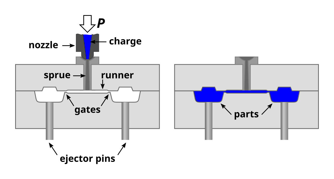
- Gate and runner strategy — simulating fill pattern, weld-line location, and pressure balance to select gate position and type before mold machining
- Parting-line and shutoff review — confirming the proposed split line is manufacturable and all shutoff angles meet minimum sealing requirements
The output is a written DFM report delivered to the customer before any tooling commitment. Product engineers get the data needed to make informed design decisions; procurement teams get confidence that the quoted mold cost is the delivered mold cost.
Get a Engineering Review Before Your Next Mold
Share your 3D model with LongTeam’s engineering team. The team will confirm which wall-thickness, draft, rib, undercut, and gate-strategy checks belong in the written DFM scope before tooling approval.
Contact Our Engineering TeamWhat to confirm before supplier review
Use the drawing, material specification, expected demand, application conditions, and acceptance requirements to turn a general process discussion into a program-specific review.
- Which drawing and 3D-model revisions control?
- What material grade and application conditions apply?
- Which features are critical to fit, function, sealing, or appearance?
- Which DFM decisions require customer approval before tooling?
Continue the engineering review
Use the related guides and capability pages to connect this topic to part geometry, tooling, molding, and qualification decisions.