What matters most
- Record cavity, location, frequency, appearance, dimensions, lot, machine, and when the defect began.
- Separate suspect material and parts while protecting approved production.
- Compare design, resin, drying, tool condition, venting, cooling, machine, process, and handling evidence.
Use a controlled corrective-action sequence
Evaluate the technical choice together with part requirements, tooling consequences, production controls, and the evidence required for approval.
Define
Record cavity, location, frequency, appearance, dimensions, lot, machine, and when the defect began.
Contain
Separate suspect material and parts while protecting approved production.
Diagnose
Compare design, resin, drying, tool condition, venting, cooling, machine, process, and handling evidence.
Verify
Confirm the correction over an agreed production window and update controls or maintenance as needed.
Technical guide
The sections below retain the detailed design, tooling, process, and quality context needed to evaluate this topic beyond the summary.
Key Takeaways
- 1 The six most common defects—flash, sink marks, short shots, warpage, weld lines, and burn marks—account for 91% of all injection molding flaws, and most trace to one of three root causes: mold design, process parameters, or material handling.
- 2 Industry data shows 80% of defects can be eliminated through systematic machine parameter adjustment alone—before any costly tooling changes are made.
- 3 Typical production scrap rates run 3–8%; structured quality controls cut those rates by 60–80% within 6–12 months—one documented case reduced defects from 6.8% to 1.2%.
- 4 The highest-leverage intervention is DFM review before steel is cut: gate location, wall thickness transitions, and cooling channel placement are mold design decisions that determine which defects are possible—and which aren’t.
Why Defects Happen: The Mold Maker’s View
The global injection molding market reached $298.7 billion in 2024, growing at a 4.5% CAGR. Yet across that enormous volume, scrap rates of 3–8% quietly drain profitability. In a facility running $1M of annual production value, that equates to $30,000–$80,000 in wasted material, labor, and machine time every year.
Most troubleshooting articles treat defects as a process problem—adjust temperatures, tweak pressures, run a design of experiments. That framing misses half the picture. As an integrated mold manufacturer and injection molder founded in 1989, LongTeam evaluates defects from both ends: the tooling design that sets the physical boundary conditions, and the molding process that operates within them. Many defects that surface at the press trace directly to decisions made weeks earlier when the mold was being designed—gate location, vent placement, cooling circuit layout, wall thickness transitions.
This guide applies that dual lens. For each of the 10 most common defects, we identify root causes across three categories—Design, Process, and Material—and provide a prioritized fix checklist aimed at faster diagnosis and fewer mold-back cycles.
Defect Frequency: Where to Focus First
Not all defects are equally common. Quality data from serial injection molding production shows six defect types account for 91% of all observed flaws. Flash alone represents more than a third of all issues:
| Defect | Share of Defects | Primary Root Cause | First Corrective Action |
|---|---|---|---|
| Flash | 35% | Process / Mold fit | Verify clamp force ≥ injection pressure × projected area; reduce pack pressure |
| Sink Marks | 25% | Design (wall thickness) | Increase hold pressure & time; reduce wall at boss/rib roots to ≤60% nominal |
| Short Shots | 18% | Process / Venting | Raise injection pressure 10–15%; clean or add vents (0.02–0.05 mm depth) |
| Warpage | 12% | Design / Cooling | Balance cooling channels; hold wall thickness variation ≤15% |
| Weld Lines | 8% | Design (gate location) | Raise melt temperature 10–15°C; relocate gate to merge weld at non-structural area |
| Burn Marks | 8% | Process / Venting | Add vents at last-fill zone; reduce injection speed in final 10–15% of stroke |
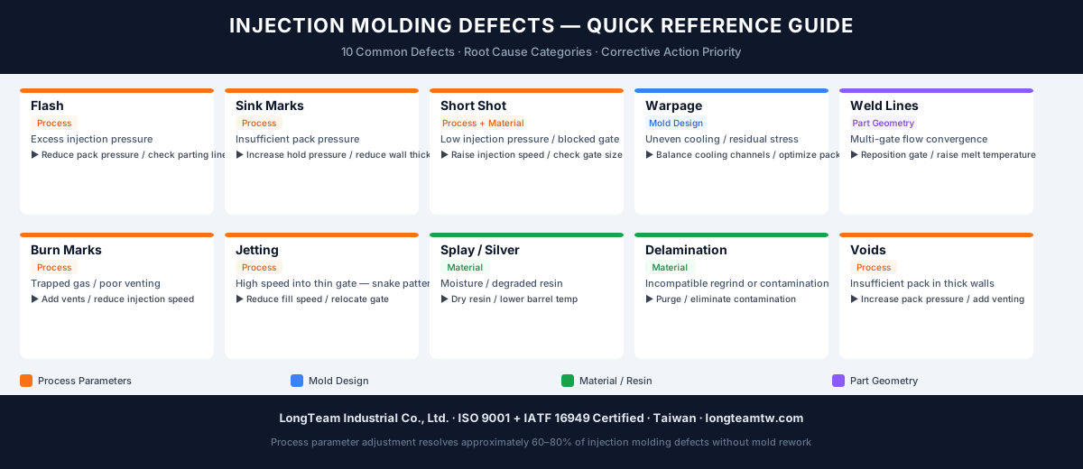
The 10 Defects: Diagnostic Reference
1. Sink Marks
Shallow depressions on the surface, typically opposite ribs, bosses, or thick-wall transitions. The exterior solidifies while the core is still molten; as the core cools and contracts it pulls the surface inward.
- Wall thickness >4 mm locally
- Rib or boss root >60% of nominal wall
- Gate undersized for section volume
- Insufficient hold pressure / time
- Early gate freeze-off
- Mold temperature too high
- High-shrinkage semi-crystalline resin (PP, PA) without adequate pack compensation
2. Warpage
Visible bending, twisting, or bowing after ejection. Caused by differential shrinkage: sections that cool faster shrink more, creating internal stresses that distort the final shape.
- Wall thickness variation >15%
- Asymmetric cooling channel layout
- Unbalanced runner system
- Uneven mold temperature across halves
- Injection speed too high (shear stress)
- Insufficient cooling time
- Anisotropic fiber-filled grades (GF-PA) require gate orientation analysis
3. Short Shots
Incomplete mold fill; the part exits the tool missing sections or thin features. Results from frozen gates, trapped air, insufficient material, or flow restriction.
- Gate undersized for flow length
- No vents at last-fill zones
- Wall too thin for flow-length-to-thickness ratio
- Injection pressure too low; raise 10–15%
- Melt temperature too low; raise 8–14°C
- Shot size set too small
- High-viscosity grade; match MFI to part geometry
- Regrind ratio too high
4. Flash
Thin fin of excess material at the parting line, core pins, or vents. Occurs when melt pressure exceeds clamping force or when mold halves no longer seal tightly.
- Worn or damaged parting surface
- Gate positioned to maximize cavity pressure at parting line
- Injection or pack pressure too high
- Clamping force insufficient for projected area
- Melt temperature too high (lowers viscosity)
- Low-viscosity grades amplify flash risk at worn tooling
5. Weld Lines (Knit Lines)
Visible seam or structural weakness where two melt fronts meet but fail to fully fuse. Common at holes, multiple gates, and complex geometry that splits flow.
- Gate location forces weld into high-stress area
- Through-holes without flow-leader compensation
- Melt temperature too low; raise 10–15°C
- Injection speed too slow at weld zone
- Mold temperature too low
- Glass-filled grades inherently weaker at weld; run flow simulation before tooling
6. Burn Marks
Black or brown discoloration at the end of fill. Caused by the “diesel effect”: trapped air in the last-fill zone compresses adiabatically and ignites, scorching the resin.
- No vents at last-fill locations
- Vent depth below 0.02 mm (chokes airflow)
- Injection speed too high in final fill stage
- Melt temperature above material processing limit
- Long residence time in barrel
- Thermally sensitive grades (POM, PVC) require barrel purging protocol
7. Jetting
Snake-like or worm-trail marks on the part surface. Occurs when plastic shoots through a small gate into open cavity space without contacting the mold wall, cooling and solidifying before it can spread and bond.
- Gate too small or positioned to fire into open space
- Gate directly opposite a large open cavity
- Injection speed too high at gate
- Melt temperature too low (high-viscosity jet)
- Low-viscosity grades jet more readily; confirm gate sizing via flow simulation
8. Splay (Silver Streaks)
Silver or white streaks on the part surface, often fanning out from the gate. Most commonly caused by moisture boiling in the barrel, material contamination, or thermal degradation.
- Sharp corners or abrupt wall transitions generate shear-induced splay
- Barrel temperature above resin degradation onset
- Back pressure too low; increase to 5–10 bar
- Moisture content too high; dry hygroscopic resins (PA, PC, ABS) to <0.02% before processing
- Contaminated regrind
9. Delamination
Thin surface layers peel away like mica flakes. Caused by incompatible materials or severe shear at the gate creating discrete layers that cannot chemically bond.
- Gate shear too high for resin viscosity (undersized gate)
- Injection speed too high near gate
- Mold temperature too low (skin freezes before bonding)
- Contamination with incompatible polymer or mold release agent
- Regrind from a different resin family mixed in
10. Voids (Vacuum Bubbles)
Interior air pockets in thick sections, invisible on the surface but detectable by X-ray or cross-section inspection. Often confused with splay; voids are enclosed and not surface-breaking.
- Wall thickness >6 mm; use coring to reduce mass
- Gate positioned so it freezes before pack phase completes
- Pack pressure too low; increase hold time
- V/P switchover point too early
- High-shrinkage resin without adequate volumetric compensation during pack
The DFM-First Philosophy: Catching Defects Before Steel Is Cut
Working through a defect list after production starts is the expensive route. Every mold-back cycle for design changes typically costs 2–6 weeks and $3,000–$15,000 per significant tooling modification. The 10 defects above are not random events: they are consequences of specific, predictable design choices that can be identified and corrected before any steel is machined.
At LongTeam, every new project begins with a DFM review before quotation is finalized. Our engineering team flags high-risk conditions—wall thickness hot spots, problematic gate locations, insufficient draft, missing vents at last-fill zones—and discusses them with the customer before tooling starts. Automotive customers requiring IATF 16949 quality standards (minimum Cpk 1.67) particularly benefit from this upstream intervention, because process capability is built on sound mold geometry, not process tuning alone.
The systematic approach pays for itself quickly: process optimization investments typically pay back within one month, while tooling modifications pay back within two months. A defect caught at design review costs nothing. The same defect discovered at first production run costs weeks. Discovered at a customer’s assembly line, it can cost everything.
Get a Engineering Review for Your Next Mold Project
LongTeam’s engineering team can review part-design risks before tooling approval. Founded in 1989, the company connects mold design with molding feedback; the review scope and deliverables are confirmed for each program.
Request a Engineering Review →What to confirm before supplier review
Use the drawing, material specification, expected demand, application conditions, and acceptance requirements to turn a general process discussion into a program-specific review.
- Is the defect limited to one cavity, lot, machine, or shift?
- What changed before the defect appeared?
- Which evidence supports the proposed root cause?
- How will the correction and recurrence prevention be verified?
Continue the engineering review
Use the related guides and capability pages to connect this topic to part geometry, tooling, molding, and qualification decisions.