What matters most
- Identify dimensions that control fit, sealing, alignment, movement, safety, or regulatory acceptance.
- Review shrinkage, anisotropy, moisture, wall sections, ribs, bosses, and feature location.
- Consider cavity layout, cooling, gates, actions, steel-safe strategy, and process window.
Tighten only the dimensions that control function
Evaluate the technical choice together with part requirements, tooling consequences, production controls, and the evidence required for approval.
Functional intent
Identify dimensions that control fit, sealing, alignment, movement, safety, or regulatory acceptance.
Material and geometry
Review shrinkage, anisotropy, moisture, wall sections, ribs, bosses, and feature location.
Tool and process
Consider cavity layout, cooling, gates, actions, steel-safe strategy, and process window.
Measurement
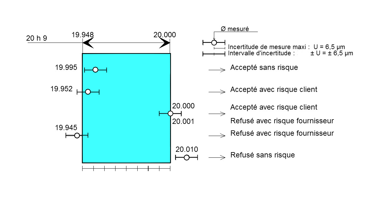
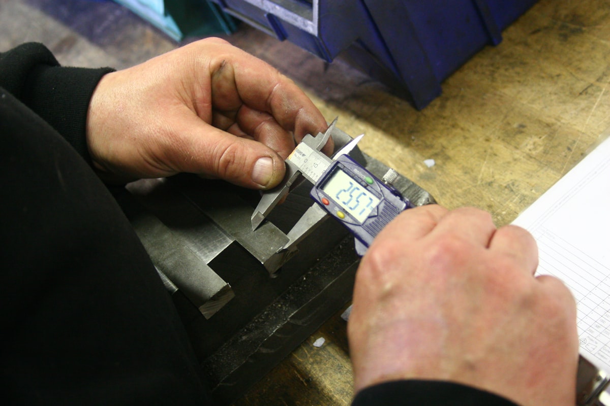
Define datums, conditioning, fixture, instrument, sampling, and measurement uncertainty.
Technical guide
The sections below retain the detailed design, tooling, process, and quality context needed to evaluate this topic beyond the summary.
An injection-molding tolerance is credible only when it is tied to a specific feature, material, datum scheme, mold concept, process window, conditioning method, and inspection plan. A number copied from a general tolerance chart is a starting point for discussion—not proof that the production process can hold that dimension.
Standard vs. tight injection molding tolerances
The useful distinction is not a universal numeric boundary between “standard” and “tight.” It is the amount of program-specific control and evidence required to protect function.
| Requirement type | How it is specified | Evidence to request | Typical cost drivers |
|---|---|---|---|
| General dimension | A drawing-wide tolerance or an applicable molded-part standard | First-article results and an agreed sampling plan | Part size, resin behavior, cavity count, measurement effort |
| Function-critical dimension | A feature-specific limit connected to fit, seal, alignment, movement, safety, or appearance | Datum-based inspection, measurement-system agreement, and trial evidence | Tool adjustment strategy, process control, fixture design, inspection frequency |
| Capability-controlled characteristic | A customer-defined requirement with an agreed statistical acceptance rule | Measurement-system analysis and capability data from the approved material, cavity, tool, and process | Run length, cavity-level reporting, monitoring, documentation, corrective action |
Legacy supplier charts may group requirements into commercial, fine, or precision classes. Those labels can help start a quotation, but they do not replace a dimensioned drawing or establish capability for a particular part.
What ISO 20457 does—and does not—tell you
ISO 20457:2018 provides possible manufacturing tolerances for plastic molded parts and a datum-system framework. It also allows additional functional specifications using the ISO geometrical product specification system. The standard does not cover every surface imperfection, override product-specific standards, or prove that one supplier can produce every listed tolerance.
Use the standard as a common language, then identify which dimensions need feature-specific limits or geometric controls. Where form, orientation, or location matters, ASME Y14.5 or the customer’s chosen GPS standard can communicate functional intent more clearly than applying tighter plus/minus limits everywhere.
Six inputs that determine dimensional capability
| Input | Why it matters | What to define before tooling |
|---|---|---|
| Function | Not every dimension carries equal product risk. | Critical interfaces, mating parts, clearance, sealing, alignment, and cosmetic zones |
| Material | Shrinkage and dimensional response vary by exact grade, filler, moisture, and processing history. | Approved resin grade, color or additive package, conditioning, and substitution rules |
| Part geometry | Wall transitions, ribs, bosses, long spans, and asymmetric sections change cooling and restraint. | Nominal walls, transitions, draft, feature support, and likely distortion modes |
| Mold concept | Gate, cooling, parting line, slides, cavity layout, and ejection influence the measured result. | Cavity strategy, gate and parting-line locations, cooling plan, steel-safe features, and adjustment access |
| Process | Packing, temperatures, cooling, and material preparation affect shrinkage and stability. | Development approach, approved process window, cavity traceability, and change control |
| Measurement | A result is meaningful only when the method, datum, fixture, timing, and uncertainty are understood. | Instrument, fixture, datum alignment, conditioning, time after molding, sample plan, and acceptance rule |
Shrinkage data does not establish production capability
Resin data sheets and standard test specimens help engineers estimate mold shrinkage, but the production part has its own flow path, wall distribution, orientation, thermal history, and constraints. ASTM D955 explains that mold and melt temperature, filling, and packing can significantly affect shrinkage, and cautions that standard specimens do not predict absolute values for parts with different geometry or processing conditions.
This is why the same nominal resin can produce different dimensional behavior across features or flow directions. Filled materials may also behave differently along and across flow. The correct mold compensation must be developed from grade-level data, simulation or engineering judgment where appropriate, and evidence from actual tool trials.
Define conditioning and measurement before comparing results
Temperature, moisture, time after molding, and part support can change the measured result. ISO 291 defines standard atmospheres for conditioning and testing plastics, but the relevant condition and timing still need to match the material, product requirement, and customer agreement.
Before first-article inspection, agree on these questions:
- Which drawing revision and datum structure control acceptance?
- When after molding will the part be measured, and under what environmental condition?
- How will flexible, curved, or easily distorted parts be supported?
- Which instrument or fixture will be used, and is its uncertainty suitable for the tolerance?
- Will results be reported by cavity, lot, or production condition?
- Which characteristics require conformance only, and which require capability evidence?
A practical tolerance review before mold release
- Mark the functional interfaces. Identify dimensions that affect fit, sealing, movement, alignment, safety, regulatory acceptance, or visible appearance.
- Separate size from geometry. Decide whether size, position, profile, flatness, or another geometric control best protects the function.
- Review the exact material and environment. Include filler, moisture response, service temperature, aging, and approved substitutions.
- Connect each critical feature to the mold. Review gate direction, parting line, actions, cooling, ejection, cavity count, and steel-safe adjustment strategy.
- Agree on measurement. Define datums, fixtures, conditioning, instruments, sample size, cavity identification, and reporting format.
- Validate with production-representative evidence. Use the approved resin, tool, cavity, process, and measurement method before treating a tolerance as demonstrated capability.
What to send for a tolerance review
A useful review package lets the mold designer distinguish functional requirements from drawing defaults. Include:
- 3D CAD and the controlled 2D drawing with units and revision;
- the exact resin grade and any approved alternatives;
- mating-part information or assembly stack-up for critical interfaces;
- marked critical-to-quality dimensions and the reason each matters;
- service temperature, moisture, load, sealing, optical, or appearance requirements;
- expected annual demand and cavity assumptions;
- the required inspection, sampling, capability, and submission format.
LongTeam can connect this review to mold design and tooling, custom injection molding, and the agreed first-article or production qualification plan. Any dimensional capability should be confirmed against the actual part and program before commitment.
What to confirm before supplier review
Use the drawing, material specification, expected demand, application conditions, and acceptance requirements to turn a general process discussion into a program-specific review.
- Which dimensions are functionally critical?
- Under what conditioning and temperature are parts measured?
- What datum and gage strategy controls inspection?
- Which dimensions require capability evidence rather than simple conformance?
Standards and source context
Confirm the current revision and the customer-specific requirements that apply to the program.
Continue the engineering review
Use the related guides and capability pages to connect this topic to part geometry, tooling, molding, and qualification decisions.