What matters most
- A snap feature should be evaluated by allowable strain and retention function rather than by one universal proportion.
- Living-hinge performance depends on suitable material, flow orientation, local geometry, and conditioning.
- Prototype materials and printed parts may not reproduce the behavior of a production molded feature.
Connect feature geometry to the assembly test
Define how the feature is assembled, what it retains, how often it moves, and what failure mode is unacceptable before finalizing the mold geometry.
Material
Confirm the production grade and relevant conditioning, fatigue, creep, and environmental requirements.
Load path
Identify insertion force, retention force, deflection, and the surfaces that stop travel.
Moldability
Review flow direction, gate position, weld lines, radii, draft, and ejection.
Verification
Test production-representative parts in the mating assembly and service environment.
Technical guide
The sections below retain the detailed design, tooling, process, and quality context needed to evaluate this topic beyond the summary.
Snap-fits and living hinges let a molded part replace screws, clips, and separate lids with geometry the tool produces for free. Designed well, they cut assembly cost and part count; designed carelessly, they whiten, creep, or snap on the line. This guide covers the design rules that decide which outcome you get — and the decisions worth settling with your molder before steel is cut.
Snap-fit fundamentals
A snap-fit is a protruding feature that deflects as parts are pushed together, then springs back to lock them. Three types cover almost every application:
- Cantilever — a flexing beam with a hook at the end. The most common and the easiest to calculate and mold.
- Annular — a ring that stretches over a groove, used for round parts like pen caps and enclosures.
- Torsional — a lever that rotates about a twisting bar, useful for latches meant to be released by hand.
Designing a cantilever that survives
The failure mode for a cantilever is over-strain during assembly. The beam must flex far enough to clear the undercut without exceeding the material's permissible strain. Practical rules:
- Respect the strain limit. Keep working strain below roughly 2-3% for unfilled polypropylene and nylon, and under 1% for glass-filled grades that are strong but brittle.
- Taper the beam. Reducing thickness toward the free end spreads bending strain along the length instead of concentrating it at the base, so the same hook can deflect further safely.
- Radius the base. A sharp inside corner is a stress riser — a fillet of at least 0.5 mm dramatically raises fatigue life.
- Separate insertion and retention angles. A shallow lead-in angle (25-35 degrees) makes assembly easy; a steeper return angle sets how much force it takes to pull apart, up to a permanent lock.
Choosing the resin first matters, because the strain limit is a material property. Our material selection guide walks through how modulus and elongation trade off for exactly these features.
Living hinges: one wall, a million cycles
A living hinge is a thin web of plastic that connects two rigid sections and flexes in place of a mechanical pivot — the classic flip-top cap. Done right it outlasts the part; done wrong it tears on the first fold.
- Material is non-negotiable. Use polypropylene or polyethylene. Their semi-crystalline structure work-hardens along the bend and tolerates millions of cycles. Engineering resins like ABS or polycarbonate crack after a few flexes.
- Get the web thickness right. Aim for roughly 0.25-0.5 mm. Too thin tears; too thick locks in residual stress and cracks.
- Place the gate to flow across the hinge. Plastic must flow through the thin web so the polymer chains orient along the bend. A hinge fed from the wrong side is weak no matter how well it is dimensioned.
- Flex it warm. Cold-working the hinge immediately after ejection, while it is still warm, aligns the crystalline structure and locks in fatigue life. Many tools include this as an in-cell step.
Where these features go wrong
Most snap-fit and hinge failures trace back to a handful of avoidable mistakes:
- Sharp corners at the beam base that concentrate stress and start cracks.
- Uniform-thickness beams that over-strain at the root while the tip barely bends.
- Wrong gate location on a living hinge, leaving the web with no chain orientation.
- Ignoring creep — a snap-fit held under constant load will slowly relax, so retention features meant to stay engaged should not rely on sustained deflection.
Settle it during DFM, not after
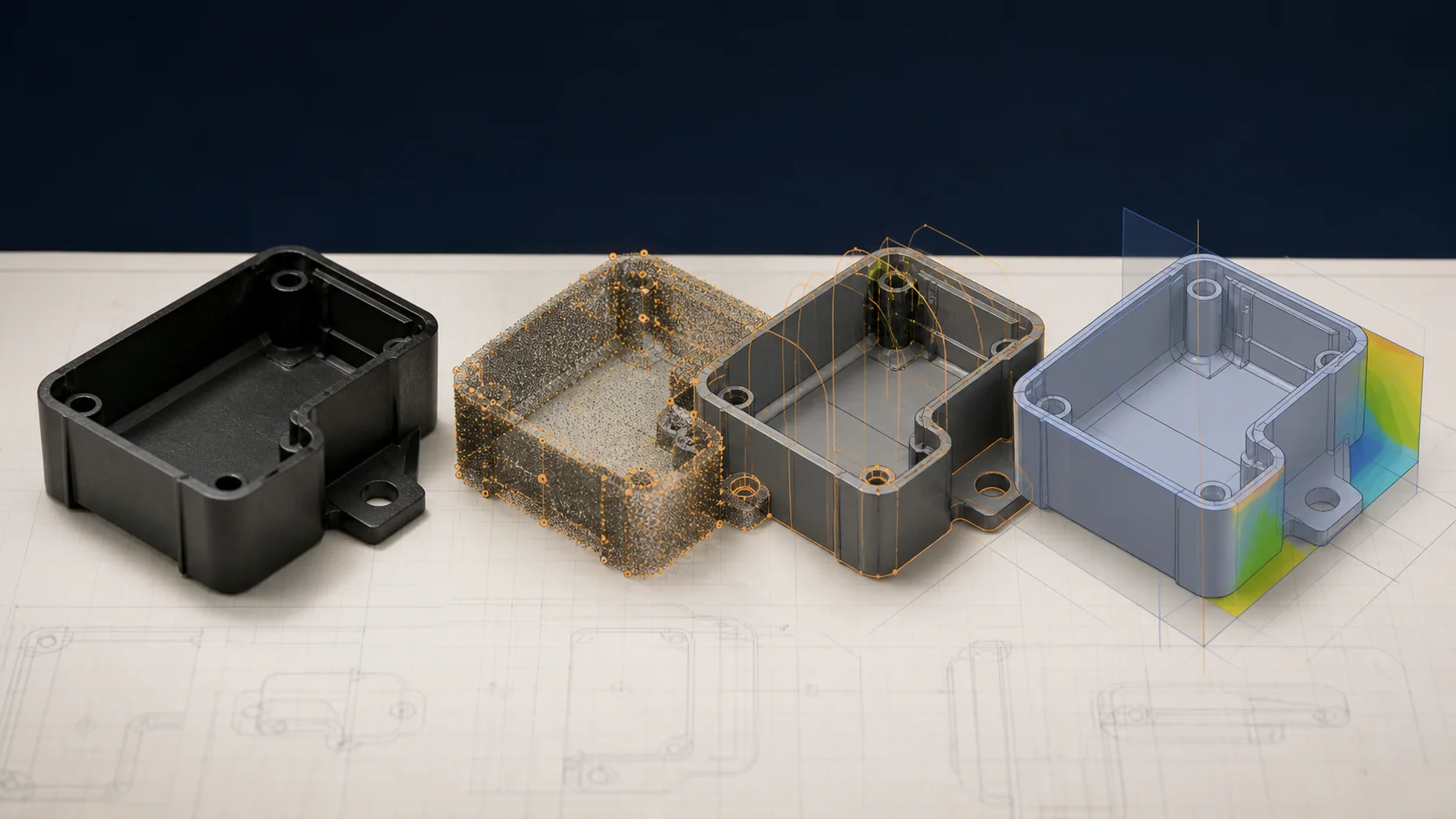
Snap-fits and hinges are cheap to change on a CAD model and expensive to change in hardened steel. Beam taper, gate position, and hinge thickness all depend on the mold layout, so they belong in the design-for-manufacturability review before tooling starts. Getting the mold design and tooling right the first time is what keeps these features out of the trial-and-error loop. If you are engineering a part around integral snap-fits or a living hinge, our team can pressure-test the geometry against the resin and gating during an initial engineering review — send us the drawing and we will flag the risks before they reach the mold.
What to confirm before supplier review
Use the drawing, material specification, expected demand, application conditions, and acceptance requirements to turn a general process discussion into a program-specific review.
- What assembly and retention forces are required?
- How many operating cycles and what environmental exposures apply?
- Will the gate and flow direction support the feature?
- What production-representative test will approve the design?
Continue the engineering review
Use the related guides and capability pages to connect this topic to part geometry, tooling, molding, and qualification decisions.