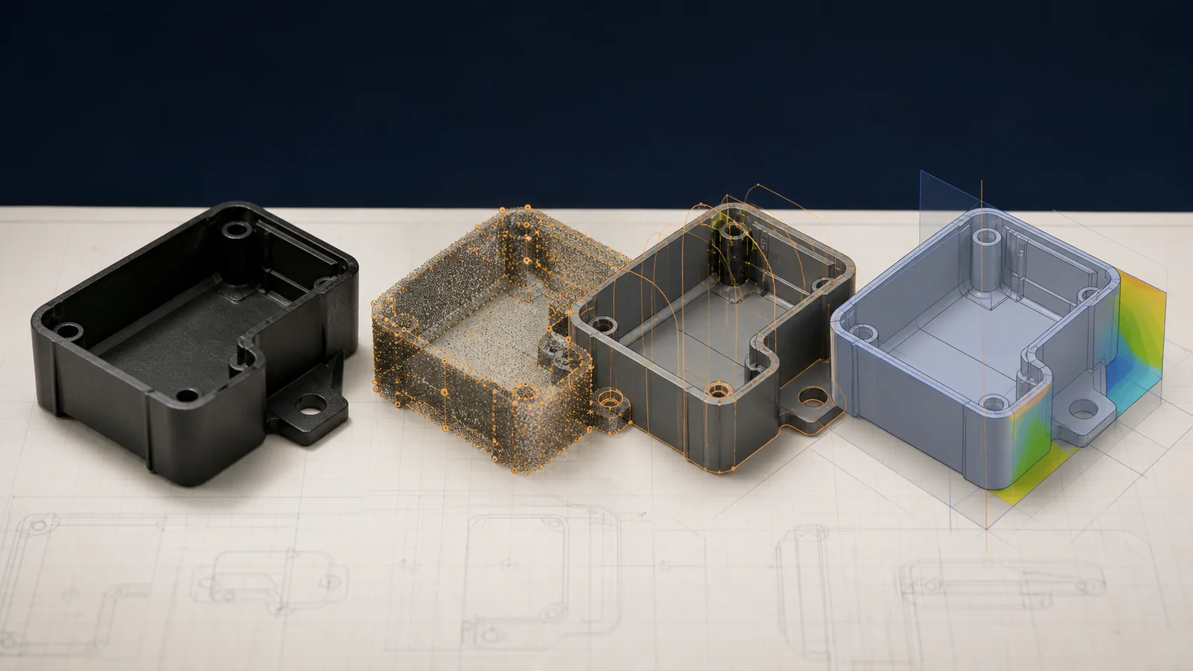
What matters most
- State whether the build evaluates geometry, assembly, user interaction, material, or functional risk.
- Close critical interfaces, tolerance intent, material, appearance, tests, and open DFM decisions.
- Choose bridge or production tooling from demand, change risk, resin, complexity, and required evidence.
Match each build to a learning objective
Evaluate the technical choice together with part requirements, tooling consequences, production controls, and the evidence required for approval.
Prototype
State whether the build evaluates geometry, assembly, user interaction, material, or functional risk.
Design freeze
Close critical interfaces, tolerance intent, material, appearance, tests, and open DFM decisions.
Tooling
Choose bridge or production tooling from demand, change risk, resin, complexity, and required evidence.
Qualification
Repeat applicable tests on production-representative material, tooling, process, and inspection methods.
Technical guide
The sections below retain the detailed design, tooling, process, and quality context needed to evaluate this topic beyond the summary.
Key Takeaways
- 1 Prototype tooling passes form-fit-function validation but systematically hides four production problems: cycle time inflation, multi-cavity tolerance stack-up, draft angle failures at scale, and gate-location weld line relocation.
- 2 Bridge tooling (aluminum or P20 steel, SPI Class 103–104, 10,000–100,000 shots, $3,000–$25,000, 4–10 week lead time) de-risks the production ramp while hardened steel production tooling is being cut.
- 3 Production mold steel is selected by three factors in priority order: annual volume, resin chemistry, and surface finish. P20 handles commodity resins to 500,000 shots; H13 handles abrasive-filled resins to 1M+ shots; S136 stainless is required for corrosive resins or mirror-polished optical and medical surfaces.
- 4 The qualification path from T0 mold trial to an approved Part Submission Warrant spans 14–22 weeks for a new injection-molded component. Five DFM changes made before production steel is ordered are the single largest determinant of whether that timeline holds.
Most hardware engineering teams encounter the gap between prototype and production the same way: a part that passed every prototype trial arrives at first-article inspection with weld lines in the wrong location, cycle times 40% longer than forecast, or warpage that never appeared in prototype. None of this is a supplier failure. It is the predictable consequence of transitioning between tooling tiers that are fundamentally different by design — and it is preventable with the right engineering decisions made before production steel is cut.
Why Prototype Tooling Hides Four Production Problems
Prototype tools (SPI Class 104–105, aluminum or soft steel, single-cavity) are optimized for speed and low initial cost, not for predicting production behavior. According to RapidDirect’s aluminum vs. steel mold analysis, aluminum has 4–10× the thermal conductivity of steel — making prototype cooling appear significantly faster than what a hardened steel production tool will deliver. Four gaps surface at nearly every prototype-to-production transition:
-
1.
Cycle time inflation
An aluminum prototype tool’s superior thermal conductivity produces cooling times 20–30% shorter than a hardened steel production tool with identical cooling circuit geometry. A 15-second prototype cycle can become 20–22 seconds in P20 or H13 steel — a 33–47% increase that makes per-unit cost projections built on prototype cycle data unreliable for production planning.
-
2.
Multi-cavity tolerance stack-up
A single-cavity prototype tool allows gate placement at the path of least resistance. An 8-cavity production tool requires balanced runner systems, and gate locations chosen for single-cavity convenience frequently become weld-line generators or cosmetic failures once replicated across a balanced multi-cavity layout — particularly in thin-walled parts where weld line strength is already marginal.
-
3.
Draft angle failures at production scale
Prototype tooling operators use manual release or hand-loaded inserts to extract parts with marginal draft angles. Automated production ejector pin layouts have no such forgiveness — 0° draft on a 50mm-deep feature that cleared prototype trials becomes a drag mark and sticking problem within the first few thousand production cycles, requiring tooling rework that delays production launch.
-
4.
Resin and process parameter misalignment
Prototype molding often uses a different resin lot or a substitute grade. Production tooling run with the actual specified resin under validated process parameters produces measurably different shrinkage profiles — particularly in crystalline resins such as nylon 6 (shrinkage 1.0–2.0%) and polypropylene (shrinkage 1.2–2.2%), where shrinkage is highly sensitive to pack pressure, mold temperature, and cooling rate.
Three Tooling Tiers — The Numbers Behind Each Decision
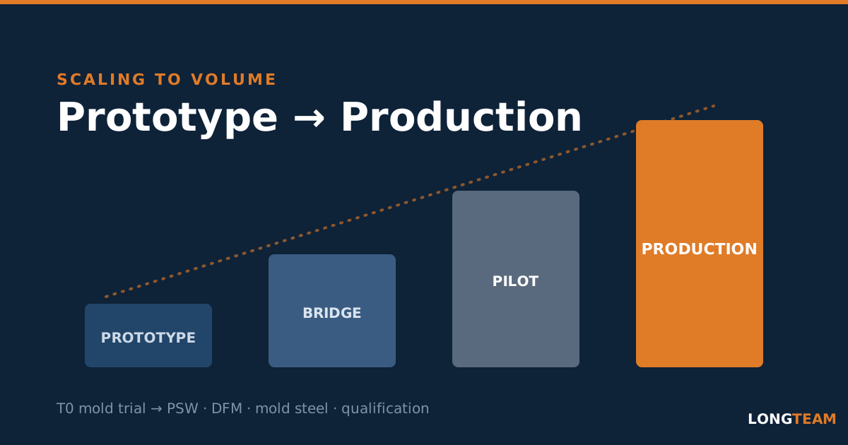
According to RPM Fast’s bridge tooling guide and mold steel selection data from ZetarMold, the three tooling tiers differ substantially in cost, shot life, lead time, and steel grade. The decision between them is driven primarily by annual volume and resin chemistry, not upfront budget alone.
| Parameter | Prototype Tooling | Bridge Tooling | Production Tooling |
|---|---|---|---|
| SPI Class | Class 105 | Class 103–104 | Class 101–102 |
| Mold Material | Aluminum alloy (7075) | Aluminum or P20 steel | P20, H13, or S136 steel |
| Shot Life | 500–10,000 | 10,000–100,000 | 500,000–1,000,000+ |
| Lead Time | 1–3 weeks | 4–10 weeks | 12–20 weeks |
| Tooling Cost | \$500–\$5,000 | \$3,000–\$25,000 | \$15,000–\$150,000+ |
| Typical Cavitation | 1 cavity | 1–4 cavities | 4–32 cavities |
| Primary Use Case | Form-fit-function validation; design iteration | Revenue ramp while production tool is being built | Sustained high-volume series production |
Steel grade selection for production tooling follows a three-factor hierarchy per Hord RT’s mold steel selection guide: annual production volume first, then resin chemistry, then required surface finish. P20 (HRC 28–33, pre-hardened) handles commodity resins up to 500,000 shots and saves 5–10 days on tool build time vs. tool steels that require vacuum hardening. H13 (HRC 48–52) is mandatory for glass-filled or abrasive resins and sustains 1,000,000+ shots. S136 stainless (13.6% chromium, HRC 48–52) is specified for corrosive resins, optical parts, or medical components — at a 60–90% cost premium over P20.
Five DFM Changes to Make Before Cutting Production Steel
Per injection molding DFM guidance updated for 2026, the majority of first-article failures at T1 are traceable to design decisions deferred from the prototype phase. These five changes, made before production steel is ordered, prevent the majority of tooling rework events:
-
1. Normalize wall thickness to ±25% of nominal
Abrupt section changes cause differential cooling, sink marks, and warpage in production. Core out sections thicker than 4mm. Any wall transition should taper or radius over a minimum length of 3× the thickness difference. Uniform wall also makes Cpk predictions from mold flow analysis actionable rather than approximate.
-
2. Confirm gate locations for multi-cavity fill balance
Run mold flow analysis on the production cavity count and runner system before finalizing gate positions. Validate that weld lines form outside structural load zones and away from Class-A surfaces. Gate relocation after production steel is cut adds \$2,000–\$8,000 in tooling rework per affected cavity and 3–6 weeks in schedule slip.
-
3. Audit and correct all draft angles to production minimums
Apply 1° minimum draft on non-textured vertical surfaces; 3–5° on textured surfaces (add 1° per 0.025mm of texture depth); 1.5° minimum on ribs. Confirm that ejector pin locations, sizes, and counts are documented and that no pin falls on a Class-A surface.
-
4. Design cooling circuits before steel is purchased
The cooling system must be part of the mold design package — not an afterthought added during T0 debug. Specify channel diameter (typically 8–12mm for commercial parts), pitch from cavity surface (1.5–2.0× channel diameter), and circuit layout. Sections unreachable by straight-drilled channels should be flagged for bubblers or conformal cooling inserts at the design stage.
-
5. Lock the production resin and obtain material certification before T0
Switching resin grade between prototype and T0 is among the most common causes of dimensional non-conformance at first article. Confirm the exact commercial grade, colorant system, and additive package. Obtain the material certification (MFR, tensile, impact, and shrinkage data) from the resin manufacturer. Process window development at T0 must be run on the certified production lot, not a substitute.
The Qualification Path from T0 to Production Release
Once the five DFM changes above are embedded in the production mold design, the formal qualification sequence runs from T0 through a series of mold trials to production part approval. According to Super-Ingenuity’s mold development process guide, a well-managed qualification sequence takes 14–22 weeks from mold design sign-off to PSW approval. Programs that run significantly longer are almost always delayed by T2 or T3 rework events seeded by DFM gaps from the prototype phase.
| Stage | Primary Purpose | Key Measurements & Acceptance Criteria | Typical Duration |
|---|---|---|---|
| T0 | First steel shot; verify fill, runner balance, and ejection | Short-shot sequence; visual inspection; no formal dimensional requirements | 1–2 weeks |
| T1 | Dimensional first article; identify steel rework list | Full dimensional layout per drawing; GD&T verification; cosmetic approval; rework list issued | 3–5 weeks |
| T2 | Post-rework reconfirmation; process window development | Dimensional conformance to drawing; Cpk ≥ 1.33 on critical features; rework list closed | 3–4 weeks |
| T3 | Production validation run; PPAP data collection | SPC study (30 consecutive shots); MSA/Gage R&R; full PPAP Level 3 package; PSW submission | 4–8 weeks |
Bridge tooling serves a critical parallel-path role during qualification. For programs with committed launch dates, a bridge tool running 1,000–30,000 production-grade parts can supply initial customer shipments while the production tool moves through T1 and T2 rework. This eliminates the binary choice between delaying launch until production tooling is perfect and shipping with prototype parts that cannot hold production tolerances.
For a detailed walkthrough of what happens at each mold trial stage — including specific acceptance criteria, engineer responsibilities, and tooling sign-off procedures — see LongTeam’s complete guide to injection mold trial stages T0 through T3.
Ready to Plan Your Production Ramp?
LongTeam Industrial builds prototype, bridge, and production injection molds in aluminum, P20, H13, and S136 steel. Our engineering team conducts production-readiness DFM reviews before production steel is ordered — identifying wall thickness issues, gate location conflicts, draft angle gaps, and cooling design requirements before they become T1 rework events. Contact us to discuss your tooling and production ramp requirements.
Request a Production-Readiness DFM Review →What to confirm before supplier review
Use the drawing, material specification, expected demand, application conditions, and acceptance requirements to turn a general process discussion into a program-specific review.
- What question must the current prototype answer?
- Which properties are not production-representative?
- What evidence is required before production-tool release?
- How will engineering changes be controlled across stages?
Continue the engineering review
Use the related guides and capability pages to connect this topic to part geometry, tooling, molding, and qualification decisions.