What matters most
- Name the finish system, grade, texture number, or approved sample that controls.
- Mark appearance zones, hidden surfaces, gate areas, parting lines, and permitted witness marks.
- Review draft, draw depth, polishing direction, texture release, vents, and repairs.
Translate finish language into an acceptance method
Evaluate the technical choice together with part requirements, tooling consequences, production controls, and the evidence required for approval.
Reference
Name the finish system, grade, texture number, or approved sample that controls.
Location
Mark appearance zones, hidden surfaces, gate areas, parting lines, and permitted witness marks.
Moldability
Review draft, draw depth, polishing direction, texture release, vents, and repairs.
Approval
Define lighting, distance, color, gloss, sample, and defect criteria for inspection.
Technical guide
The sections below retain the detailed design, tooling, process, and quality context needed to evaluate this topic beyond the summary.
A surface-finish callout is not a complete appearance specification
SPI, VDI, or proprietary texture codes can identify a starting reference, but a code alone does not define what the molded part must look like. The result also depends on the exact resin and color, part geometry, gate and weld-line locations, mold preparation, texture direction, process conditions, and viewing method.
A release-ready specification should answer four questions: which reference controls, where it applies, whether the geometry can mold and release it, and how the customer will approve the result. This prevents a toolmaker, molder, and buyer from each interpreting “matte,” “gloss,” or “fine texture” differently.
Separate tool finish, molded appearance, and decoration
| Layer | What it controls | What to specify |
|---|---|---|
| Mold-surface preparation | The cavity surface produced by polishing, paper, stone, blasting, EDM, laser, or chemical texturing | Named reference system, grade or pattern, revision, location, direction, and approved plaque |
| As-molded appearance | The visible part after resin, color, geometry, gating, cooling, and processing interact with the tool | Resin grade, color, cosmetic zones, viewing conditions, permitted defects, gloss or color method, and master sample |
| Post-mold decoration | Paint, printing, coating, plating, laser marking, or another secondary finish | Preparation, color and gloss target, masking, adhesion, durability, and approval tests |
Keep these layers separate on the drawing and in the approval plan. A tool-finish designation does not by itself establish the gloss, color, defect visibility, or decorated appearance of the production part.
How to use SPI, VDI 3400, and Mold-Tech references
SPI / PLASTICS mold-finish references
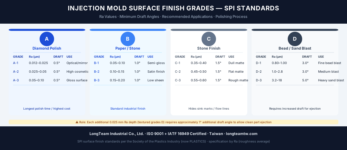
The PLASTICS AR-106 Mold Finish Guide provides physical finish samples and groups preparation methods as diamond buff (A), paper (B), stone (C), and dry blast (D). Specify the relevant grade and use a current physical reference when appearance matters. Do not convert the grade into a universal roughness, draft, cost, or optical-performance promise without program-specific evidence.
VDI 3400 references
The official VDI 3400 document concerns electrical-discharge machining terminology, processes, and applications. Texture numbers described commercially as “VDI 3400” should therefore be tied to the actual plaque, supplier reference, and revision being used. Avoid treating an internet conversion chart as proof that a VDI designation and an SPI finish will create the same molded appearance.
Mold-Tech and other proprietary textures
For a proprietary texture, put the exact texture identifier and controlled reference on the drawing. Confirm the plaque, pattern scale, orientation, blend boundaries, repair method, and applicable revision with the engraver and moldmaker. Draft and release requirements should be reviewed against the actual texture depth, draw direction, resin, wall geometry, and tool construction before steel is finalized.
Choose the finish from the decision the surface must support
| Desired result | Reference to define | Engineering review | Approval evidence |
|---|---|---|---|
| High-gloss or transparent appearance | Polish reference plus resin, color, and controlled cosmetic zones | Flow path, gate and weld lines, steel condition, polishing direction, wall transitions, and handling | Approved molded sample under defined lighting and viewing conditions; instrument method where required |
| Satin or matte appearance | Physical finish plaque or agreed tool-preparation reference | Uniformity, draw direction, release, vents, ejection contact, and local geometry | Boundary sample showing acceptable sheen, color, flow, and witness marks |
| Patterned or proprietary texture | Exact texture code, supplier, revision, plaque, location, and orientation | Texture depth, draft, shutoffs, slides, parting lines, blend zones, and repair access | Approved plaque followed by a production-material molded sample |
| Controlled color or gloss | Master color, resin grade, finish, measurement method, and viewing geometry | Material lot, wall thickness, process window, texture, and instrument correlation | Approved master and agreed measurement limits using the same test method |
Define cosmetic acceptance before the first trial
The PLASTICS AQ-103 Cosmetic Specifications emphasizes consistent viewing conditions and agreed acceptance criteria. A practical appearance plan should define:
- Cosmetic zones: identify primary viewing surfaces, secondary surfaces, hidden areas, edges, gates, parting lines, and assembly interfaces.
- Inspection conditions: document lighting, viewing distance, viewing angle, inspection time, background, and whether visual aids are permitted.
- Defect language: define how flow marks, weld lines, gloss variation, splay, blush, sink, scratches, and tooling witness marks will be judged.
- Physical standards: control the plaque, molded master, boundary sample, color master, revision, storage, and replacement process.
- Measurement method: where numeric gloss is required, specify the instrument geometry, preparation, locations, and comparison method. ASTM D2457 notes that plastic gloss is complex and results should be compared using the same method and general material type.
- Production control: state whether approval applies by cavity, resin or color lot, process condition, production lot, and approved change.
Review texture, draft, and release together
Texture can increase resistance as the part leaves the cavity, but no single draft-angle rule applies to every design. The required release condition depends on texture depth and orientation, draw length, resin behavior, wall flexibility, shrinkage, cavity or core location, shutoffs, slides, and ejection strategy.
Before applying texture, mark the draw direction and every textured wall, then ask the texture supplier and moldmaker to confirm the release strategy. Resolve transitions between polished and textured areas, parting lines, lifters, inserts, and repair boundaries while changes are still practical. The related draft-angle design guide explains how to connect draft decisions to part geometry and tooling.
What to send for a surface-finish review
- 3D CAD and the controlled 2D drawing with revision and units;
- marked cosmetic zones, hidden areas, texture boundaries, and permitted witness locations;
- the named finish system, exact grade or texture code, supplier, revision, and physical plaque or sample;
- the exact resin grade, color, filler, additives, and approved alternatives;
- application context, viewing direction, lighting, cleaning, handling, and wear exposure;
- color, gloss, defect, and dimensional acceptance criteria with the inspection method;
- known gate, parting-line, shutoff, ejection, decoration, assembly, and annual-demand requirements.
LongTeam can connect the appearance specification to mold design and tooling and custom injection molding. Final finish and appearance acceptance should be based on the agreed reference and production-representative molded samples—not on a generic chart alone.
What to confirm before supplier review
Use the drawing, material specification, expected demand, application conditions, and acceptance requirements to turn a general process discussion into a program-specific review.
- Which finish reference and revision controls?
- Where are Class-A or other controlled surfaces?
- How does texture affect draft and part release?
- Will a physical plaque or molded sample approve appearance?
Continue the engineering review
Use the related guides and capability pages to connect this topic to part geometry, tooling, molding, and qualification decisions.