What matters most
- Use grade-level shrinkage, filler, moisture, crystallinity, and conditioning information.
- Review uneven walls, ribs, bosses, corners, long spans, asymmetry, and assembly restraint.
- Evaluate gate location, packing, cooling balance, cavity layout, ejection, and process window.
Diagnose dimensional change across the whole system
Evaluate the technical choice together with part requirements, tooling consequences, production controls, and the evidence required for approval.
Material
Use grade-level shrinkage, filler, moisture, crystallinity, and conditioning information.
Geometry
Review uneven walls, ribs, bosses, corners, long spans, asymmetry, and assembly restraint.
Tool and process
Evaluate gate location, packing, cooling balance, cavity layout, ejection, and process window.
Measurement
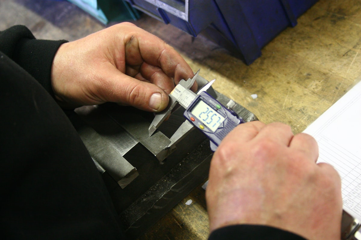
Define time after molding, conditioning, temperature, datums, fixtures, and part support.
Technical guide
The sections below retain the detailed design, tooling, process, and quality context needed to evaluate this topic beyond the summary.
Key Takeaways
- 1 Semi-crystalline resins (PP, PA66, POM) shrink 1.5–3.5% — three to six times more than amorphous resins (ABS, PC) — because crystallization adds a second contraction phase beyond simple thermal cooling.
- 2 Warpage is caused by differential shrinkage — when adjacent sections of the same part contract at different rates, internal stresses accumulate and bend the part on ejection.
- 3 Holding pressure is the single most controllable process lever: each 10 MPa increase reduces linear shrinkage by 0.05–0.15%, depending on material and gate geometry.
- 4 CAE simulation (Moldflow, Moldex3D) identifies warpage risk before steel is cut at €2,000–10,000 per project — versus €10,000–50,000+ to correct a mold after production has started.
Every injection-molded part shrinks. Every engineer who has received a first-article report with out-of-spec dimensions knows the frustration of discovering that shrinkage was underestimated, or that a flat panel that looked perfect in CAD came out bowed. This guide explains the physics driving both phenomena, quantifies them by material family, and describes the process and mold design levers that keep dimensions within tolerance — before and after steel is cut.
Why Every Thermoplastic Shrinks — and Why the Amount Varies So Much
Shrinkage is thermal physics: plastics are processed at 200–300°C and ejected into a room-temperature environment. As the melt cools, it loses volume. The formula used by mold designers to compensate is:
Dm = mold cavity dimension | Dp = final cooled part dimension
The key variable is molecular structure. Amorphous polymers — where chains remain randomly tangled during cooling — shrink modestly and isotropically. Semi-crystalline polymers undergo a second contraction event: as temperature falls through the crystallization point, chains pack into ordered lattice structures, releasing additional volume. This is why PP shrinks 1.5–2.5% while ABS shrinks only 0.4–0.7%.

Glass fiber reinforcement changes the picture significantly. Fibers mechanically restrain the polymer matrix, reducing absolute shrinkage by 50–80% in the fiber-alignment direction — but also introducing anisotropy. PA66-GF30 shrinks approximately 0.3% in the melt-flow direction versus 0.7% in the transverse direction, per TEDE Solutions (2026). This ratio must be factored separately into cavity dimension calculations for both axes.
| Material | Structure | Shrinkage Range | Shrinkage Type | Primary Driver |
|---|---|---|---|---|
| ABS | Amorphous | 0.4–0.7% | Isotropic | Thermal contraction only |
| PC | Amorphous | 0.5–0.7% | Isotropic | Thermal contraction only |
| PMMA (Acrylic) | Amorphous | 0.4–0.8% | Isotropic | Thermal contraction only |
| PP homopolymer | Semi-crystalline | 1.5–2.5% | Isotropic | Thermal + crystallization |
| PA66 (Nylon 66) | Semi-crystalline | 1.0–2.0% | Isotropic | Thermal + crystallization |
| POM (Acetal) | Semi-crystalline | 1.8–3.0% | Isotropic | High crystallinity |
| HDPE | Semi-crystalline | 1.5–4.0% | Isotropic | Very high crystallinity |
| PA66-GF30 | Semi-cryst. + fibers | 0.3–0.7% | Anisotropic | Fiber restraint + flow alignment |
| PP-GF30 | Semi-cryst. + fibers | 0.3–1.0% | Anisotropic | Fiber restraint + flow alignment |
An often-overlooked phenomenon is post-mold shrinkage: dimensional changes continuing for hours to days after ejection as the part reaches thermal and crystalline equilibrium. Per Plastics Technology, parts must be conditioned to ASTM D955 / ISO 294 conditions for at least 40 hours before first-article inspection. Dimensions taken immediately after ejection from a warm tool consistently overstate part size and produce false-acceptance conditions.
The Three Root Causes of Warpage
Warpage is differential shrinkage expressed as geometry. When adjacent zones of a part contract at different rates, residual internal stresses accumulate; once the part is ejected from the constraining cavity, those stresses relieve themselves as out-of-plane distortion. Three primary mechanisms drive this behavior:
1. Non-Uniform Cooling
The cavity-side face cools faster than the core-side when cooling channels are asymmetric or insufficient. The faster-cooling face contracts first, pulling the part into a bow. A mold-side temperature difference as small as 10°C can produce 0.5 mm of deflection per 100 mm of span in thin-wall PP.
2. Fiber Orientation
In glass-fiber-filled resins, fibers align with melt flow near the gate and perpendicular to it at flow fronts. Because fibers resist shrinkage along their axis, in-flow and cross-flow shrinkage diverge — creating a twist or bow even in geometrically symmetric parts. PA66-GF30 shows ~0.3% in-flow vs. ~0.7% cross-flow per TEDE Solutions.
3. Non-Uniform Packing
Regions near the gate receive high packing pressure, compressing the melt and reducing local shrinkage. Regions far from the gate — long flow paths or thin walls — receive lower effective packing, yielding higher shrinkage. The pressure gradient produces complex internal stress states that manifest as warpage patterns tied to gate placement.
A quantitative estimate for flat-plate warpage uses: δ = ΔS × L / (2 × t), where δ is deflection, ΔS is differential shrinkage between faces, L is unsupported span, and t is wall thickness. A PP plate with 1% differential shrinkage, 200 mm span, and 3 mm wall produces 0.33 mm of deflection — exceeding the ±0.2 mm flatness tolerance typical of precision fit parts. Gate position, cooling circuit layout, and wall uniformity are the primary design levers to minimize ΔS before steel is cut.
Process Variables That Control Shrinkage and Warpage
Before modifying a mold, process optimization is the first line of defense — it is reversible, zero-tooling-cost, and often sufficient for parts near the tolerance boundary. Three parameters have the largest documented impact:
Holding pressure is the single most effective shrinkage lever per published engineering data. Each 10 MPa increase reduces linear shrinkage by approximately 0.05–0.15%, depending on material and gate geometry. Effective holding pressure ranges are 40–70 MPa for unfilled PP and 50–100 MPa for PA66-GF30. Pressure must be maintained until the gate freezes off — premature cutoff prevents material compensation and increases dimensional scatter. A gate freeze-off study — incrementally reducing hold time while monitoring shot weight — identifies the minimum effective hold time at zero tooling cost.
Mold temperature governs crystallization rate and extent. For PP, a 40°C difference in set point (20°C vs. 60°C) produces shrinkage variation of 0.5–0.8 percentage points — dramatic for dimensional control. Higher mold temperatures allow slower, more complete crystallization: higher total shrinkage but better uniformity. Lower temperatures quench the surface quickly, creating a crystallinity gradient through the wall that is a direct warpage driver. For warpage-sensitive parts, mold temperature uniformity within ±5°C across the cavity is as critical as the absolute set point.
Cooling time must be sufficient to achieve structural rigidity before ejection forces are applied. Cooling time scales approximately with the square of wall thickness. For a 3 mm PP wall at standard conditions, approximately 18 seconds of cooling time is required before safe ejection. Premature ejection causes post-ejection warpage as the warm, soft core continues to contract against the already-cooled skin — a failure mode common when cycle times are pushed aggressively without validation.
CAE Simulation and Inverse Contouring: Engineering the Mold Before Cutting Steel
When process optimization cannot achieve dimensional targets — as is common in thin-walled glass-filled parts with complex geometry — the engineering toolkit expands to mold design corrections.
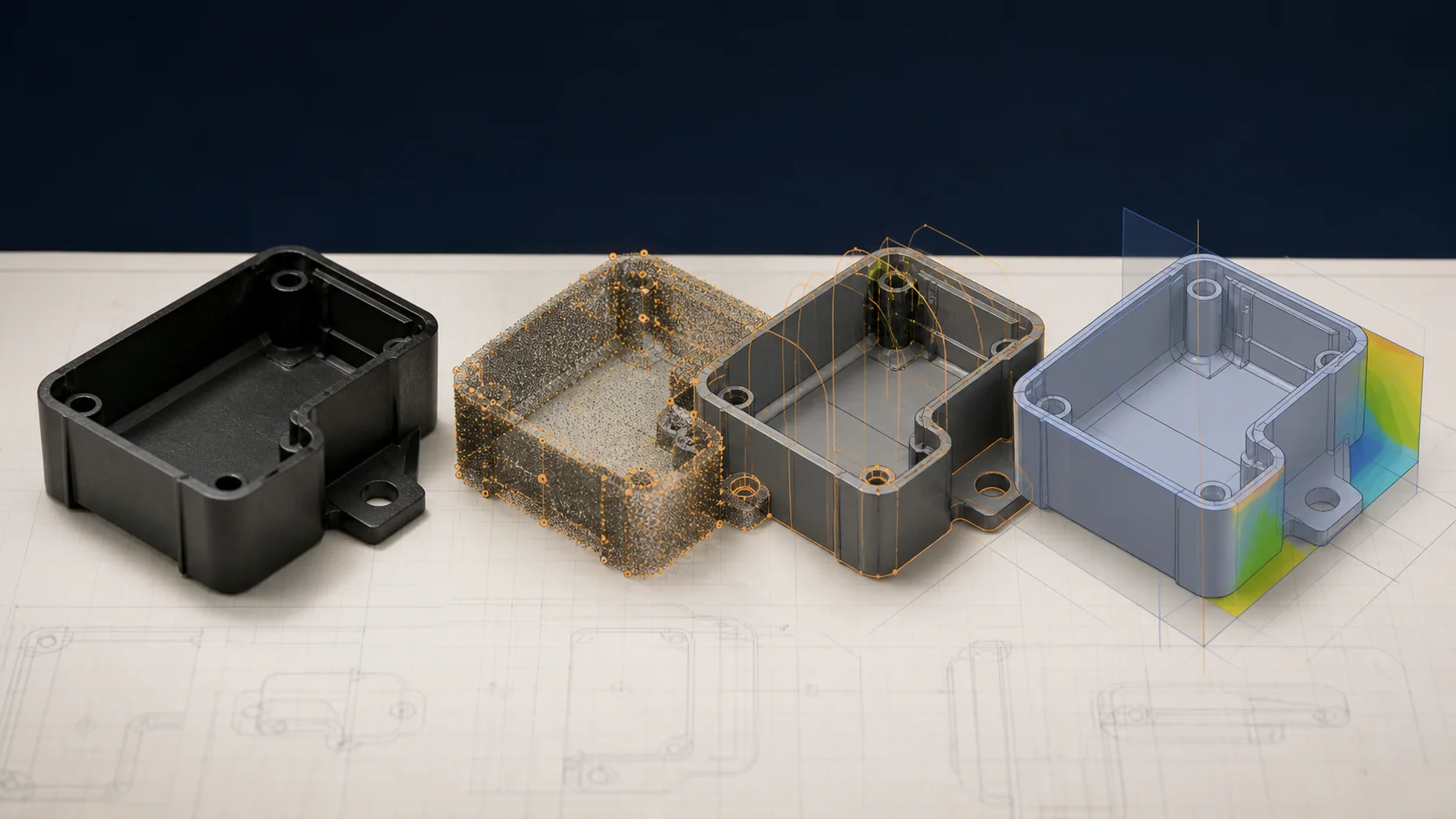
CAE simulation (Moldflow, Moldex3D, Sigmasoft) runs virtual mold-filling, packing, cooling, and warpage prediction before any steel is ordered. Analysis cost typically ranges €2,000–10,000 per project per industry benchmarks from TEDE Solutions — a clear investment when corrective mold modifications cost €10,000–50,000 and introduce 4–8 weeks of program delay. Outputs include shrinkage contour maps, warpage vector plots, and fiber orientation predictions that enable gate repositioning, cooling circuit redesign, and wall thickness optimization before the tool is ordered.
Inverse contouring intentionally builds the mold cavity in the opposite direction of the expected warpage, so the distorted ejected part arrives at the correct geometry. A peer-reviewed study in MDPI Polymers (2025) validated this approach on PBT-GF30 automotive components: starting from 1.67 mm initial warpage, response-surface process optimization reduced deflection to 0.76 mm (−61%); adding inverse contouring reduced it further to ±0.30 mm — a total 82% warpage reduction. This confirms inverse contouring as a mature engineering solution for precision parts in fiber-filled resins where process optimization alone is insufficient.
Dimensional sign-off at any stage should comply with ASTM D955 / ISO 294 conditioning: 23°C ±2°C, 50% RH, 40 hours minimum before measurement. Parts inspected immediately off the press from a warm tool will show inflated dimensions and produce incorrect process windows.
Is Warpage or Dimensional Scatter Holding Up Your Program?
LongTeam’s engineering team performs mold-filling simulation, gate freeze-off studies, and documented process window development as standard practice for new programs. Whether you are still in DFM review or troubleshooting an existing tool, we can assess shrinkage risk and identify the shortest path to first-article conformance.
Contact LongTeam →What to confirm before supplier review
Use the drawing, material specification, expected demand, application conditions, and acceptance requirements to turn a general process discussion into a program-specific review.
- Is the issue uniform shrinkage, directional shrinkage, or distortion?
- When and under what conditions are parts measured?
- Which geometry or thermal imbalance matches the observed direction?
- How will tool and process changes be verified?
Continue the engineering review
Use the related guides and capability pages to connect this topic to part geometry, tooling, molding, and qualification decisions.