What matters most
- Define nominal walls, flow lengths, transitions, ribs, openings, cosmetics, loads, and assembly conditions.
- Confirm flow behavior, degradation limits, reinforcement, color, and application requirements.
- Review gates, vents, runner, cooling, steel support, injection response, clamp, and ejection.
Treat thin walls as a system-level requirement
Evaluate the technical choice together with part requirements, tooling consequences, production controls, and the evidence required for approval.
Part
Define nominal walls, flow lengths, transitions, ribs, openings, cosmetics, loads, and assembly conditions.
Material
Confirm flow behavior, degradation limits, reinforcement, color, and application requirements.
Tool and machine
Review gates, vents, runner, cooling, steel support, injection response, clamp, and ejection.
Validation
Check fill balance, dimensions, weight, appearance, strength, handling damage, and process stability.
Technical guide
The sections below retain the detailed design, tooling, process, and quality context needed to evaluate this topic beyond the summary.
Key Takeaways
- 1 Thin-wall molding is formally defined by a wall thickness ≤1.0 mm or a flow-length-to-wall-thickness ratio (L/t) greater than 150:1 — the threshold at which conventional injection pressures and fill speeds are insufficient to complete the shot before the melt freezes.
- 2 The process requires injection speeds of 300–600 mm/s and cavity pressures up to 35,000 psi — roughly 2–3× the pressures seen in conventional molding — placing significant demands on mold steel selection, gate design, and clamp tonnage calculations.
- 3 Cycle times of 3–6 seconds (versus 8–15 seconds for conventional molding) and per-part material reductions of 20–30% give thin-wall components a decisive cost advantage in high-volume production runs exceeding 100,000 parts per year.
- 4 The three pillars of thin-wall defect prevention are: high-melt-flow resin selection, balanced gate and runner geometry, and rapid conformal cooling — all of which must be engineered before steel is cut, since post-mold corrections are costly and rarely sufficient.
Smartphone bezels, IV syringe barrels, food-container lids, and laptop housings share a common manufacturing challenge: they are too thin for conventional injection molding to fill reliably. The solution — thin-wall injection molding — is a distinct process discipline governed by different machine specifications, mold designs, and material requirements than standard production. This guide covers what changes at the process level, which materials perform reliably at sub-millimeter walls, and how to engineer out the defects that cause most thin-wall programs to fail at T1.
What Is Thin-Wall Injection Molding?
Thin-wall injection molding is defined by two criteria that can apply independently. The strict geometric definition is a nominal wall thickness at or below 1.0 mm. The process-based definition — used by engineers who need a more practical threshold — is a flow-length-to-wall-thickness ratio (L/t) greater than 150:1, meaning the molten plastic must travel more than 150 times the wall thickness before the cavity is filled. According to Kemal Manufacturing’s 2025 process guide, once the L/t ratio climbs above 150:1, the melt begins to freeze against the mold wall before completing the fill on a standard-speed machine — making high-speed injection mandatory, not optional.
This distinguishes thin-wall molding from ordinary DFM wall-thickness guidance (which targets uniformity and sink-mark avoidance) and makes it a separate capability that a molder must specifically equip for. Standard machines operate at 50–150 mm/s injection speed; thin-wall production requires 300–600 mm/s. Standard cavity pressures run 10,000–15,000 psi; thin-wall pressures peak at up to 35,000 psi. These differences place specific requirements on machine selection, mold steel grade, and gate engineering that must be resolved before a program starts.

Process Requirements: Speed, Pressure, and Cooling
Three process parameters govern thin-wall molding success: injection speed, cavity pressure, and cooling time. All three are tightly linked — higher speed increases pressure, and thinner walls cool faster, which is simultaneously an advantage (shorter cycle times) and a risk (incomplete fill if injection speed is not matched to the freeze-off time of the resin).
Cycle times for thin-wall parts run 3–6 seconds, compared to 8–15 seconds for conventional molding, according to data compiled by Kemal Manufacturing. This 50–60% reduction in cycle time is the primary reason thin-wall design is economically superior for volumes above 100,000 parts per year. A packaging manufacturer that redesigned a container from 2.5 mm to 1.0 mm walls reported a 20% reduction in resin consumption, translating to over $200,000 in annual material savings.
| Process Parameter | Conventional Molding | Thin-Wall Molding | Implication |
|---|---|---|---|
| Injection speed | 50–150 mm/s | 300–600 mm/s | Fills cavity before melt freezes at thin sections; requires servo-driven or high-speed hydraulic press |
| Peak cavity pressure | 10,000–15,000 psi | Up to 35,000 psi | Requires hardened mold steel (H13 or S136), robust parting-line seals, and heavier clamp tonnage |
| Cycle time | 8–15 seconds | 3–6 seconds | 50–60% throughput increase at equivalent machine capacity; critical economic advantage at high volumes |
| Material use per part | Baseline | 20–30% less | Lower resin cost and reduced part weight; packaging example: 20% resin reduction = $200,000 annual savings |
| Clamp tonnage | Standard (projected area × 2–4 tons/in²) | Higher (elevated cavity pressure multiplier) | Prevents flash at elevated fill pressures; must be recalculated vs. standard tooling assumptions |
Cooling design is equally critical. Because thin walls transfer heat to the mold more quickly than thick walls, small inconsistencies in cooling-channel layout produce proportionally larger temperature gradients across the part — causing warpage. Conformal cooling channels that follow the contour of the cavity wall (achievable through additive-manufactured mold inserts) reduce hot-spot temperature differentials by 15–25°C versus conventional straight-line channels and are increasingly standard on high-cavitation thin-wall tools.
Material Selection for Thin-Wall Production
Not every engineering resin is suitable for thin-wall production. The single most important material property is melt flow rate (MFR): resins with higher MFR values fill long, narrow channels more easily before freezing. Material selection should be locked before tool design begins, because gate size, runner diameter, and injection speed targets all depend on resin rheology. According to Xometry’s thin-wall process reference, standard-grade resins with MFR below 20 g/10 min are generally unsuitable for walls below 0.8 mm without significant process compensation.
| Material | Injection Speed Range | Mold Temperature | Primary Applications | Key Advantage |
|---|---|---|---|---|
| PP (Polypropylene) | 300–600 mm/s | 20–50°C | Food containers, medical trays, disposable packaging | Excellent MFR; best choice for walls ≤0.6 mm |
| PS (Polystyrene) | 250–500 mm/s | 20–40°C | Transparent packaging, laboratory trays, cosmetic covers | Optical clarity; low warpage tendency in thin sections |
| ABS | 200–400 mm/s | 50–80°C | Smartphone housings, laptop bezels, wearable enclosures | Good surface finish; paintable; balanced impact resistance |
| PC (Polycarbonate) | 200–400 mm/s | 80–120°C | Protective covers, optical lenses, automotive interior panels | High impact strength; heat resistance; dimensional stability |
| PEI (Ultem®) | 150–300 mm/s | 140–180°C | Aerospace connectors, medical sterilizable parts, high-heat housings | High-heat performance; inherent flame retardancy; FDA compliance |
Common Defects and How to Prevent Them
Thin-wall molding concentrates process risk: the same combination of high speed, elevated pressure, and rapid solidification that makes the process efficient is what makes it unforgiving of design or tooling errors. A 2025 process analysis by SilkBridge reports that approximately 40% of thin-wall defects trace to wall-thickness design errors made before tooling begins. The remaining failures divide between gate and runner design (flow imbalance, weld lines, burn marks) and cooling system design (warpage, sink marks).
| Defect | Root Cause | Prevention Strategy |
|---|---|---|
| Short shots | Melt freezes before fill completes; insufficient injection speed or melt temperature for the L/t ratio | Increase injection speed to 300+ mm/s; raise melt temperature; optimize gate location to minimize flow length |
| Warpage | Uneven cooling creates differential shrinkage across thin sections; residual stress from high-speed fill | Balance cooling channels across both mold halves; use conformal cooling; maintain uniform wall thickness throughout part geometry |
| Weld lines | Cold flow fronts meeting at low temperature without sufficient fusion pressure to bond cleanly | Raise melt temperature; increase injection speed; reposition gates to shift weld-line location away from structural or cosmetic surfaces |
| Burn marks | Trapped air at end-of-fill areas ignites under high-speed adiabatic compression | Add venting at last-fill areas; reduce injection speed in final fill phase; inspect and clean vent slots every PM cycle |
| Sink marks | Abrupt thick-to-thin wall transitions create localized shrinkage voids as the part cools | Enforce wall-thickness uniformity in design; eliminate abrupt transitions; extend packing pressure phase duration |
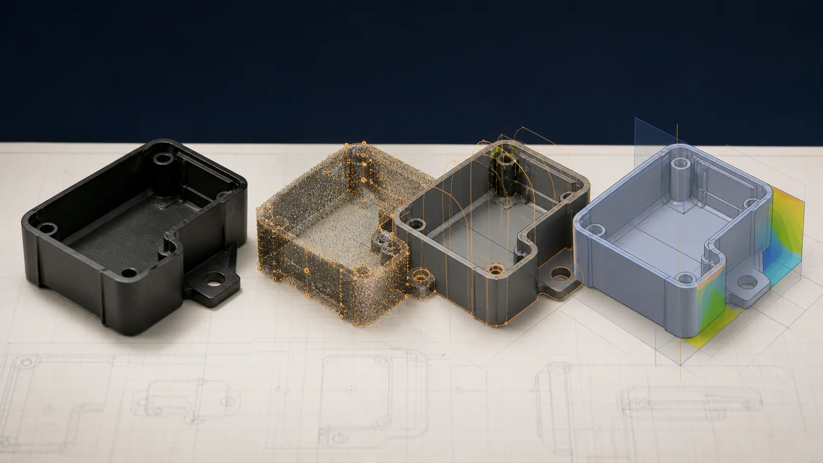
Mold flow simulation (Moldex3D or Autodesk Moldflow) run before tooling approval is the most cost-effective defect prevention available. Simulation identifies short-shot risk, weld-line location, and cooling imbalance at the design stage — when corrections cost nothing — rather than at T1, where a gate relocation or cooling-channel modification can add $8,000–$25,000 in tooling cost and four to six weeks of program delay.
Evaluating Thin-Wall Capability for Your Next Program?
Founded in 1989, LongTeam supports injection-molded component programs for automotive, electronics, and medical-device applications. Our engineering team can assess your part geometry, recommend resin grades with suitable MFR, and review mold flow simulation data before committing to steel. Contact us to discuss your thin-wall production requirements.
What to confirm before supplier review
Use the drawing, material specification, expected demand, application conditions, and acceptance requirements to turn a general process discussion into a program-specific review.
- Why does the part require the proposed wall section?
- Has flow feasibility been reviewed with the exact resin?
- Can the proposed tool and machine control the required process window?
- Which functional tests approve the lightweight design?
Continue the engineering review
Use the related guides and capability pages to connect this topic to part geometry, tooling, molding, and qualification decisions.