Decision 01 · Process fit
Decide whether injection molding fits your part
Injection molding is usually evaluated against design maturity, expected demand, geometry, material requirements, and the cost of alternative processes. There is no universal volume threshold because part size, resin, cavity count, tool construction, cycle requirements, and production risk change the break-even point.
| Project signal | What it suggests | Question to resolve |
|---|---|---|
| Stable geometry and repeatable demand | Dedicated tooling may be justified | Which tool architecture supports the forecast and change risk? |
| Ribs, bosses, snaps, texture, or integrated features | Molding can consolidate useful geometry | Can those features fill, cool, release, and be inspected? |
| Design still changes frequently | Prototype or bridge methods may be safer first | Which unknown must the next build answer? |
| Uncertain demand or a very small quantity | Compare machining or additive production | Does tooling create enough lifecycle value? |
What this means for your part: define what the next build must prove before choosing the production process.
Decision 02 · Machine cycle
Understand what happens during each molding cycle
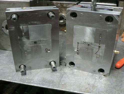
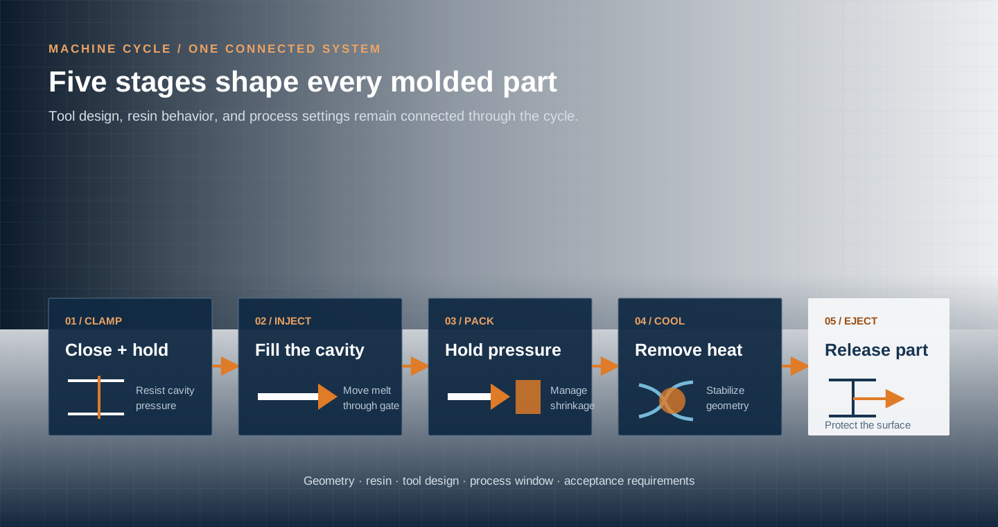
Clamp, inject, pack, cool, and eject are sequential machine stages. Each stage responds to the part geometry, resin behavior, mold design, and process settings rather than operating as an isolated step.
Decision 03 · Program path
Connect the drawing to production release
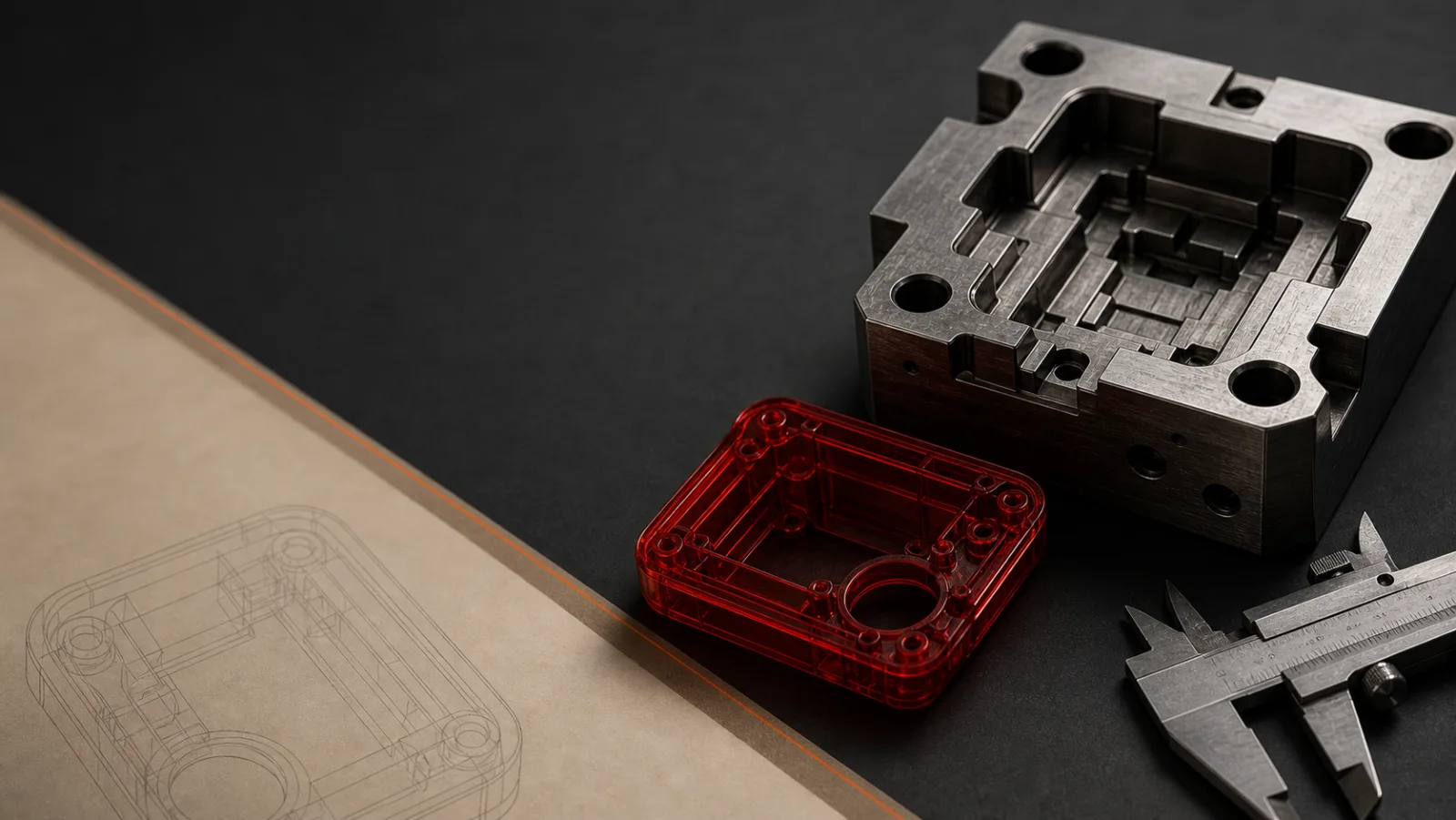
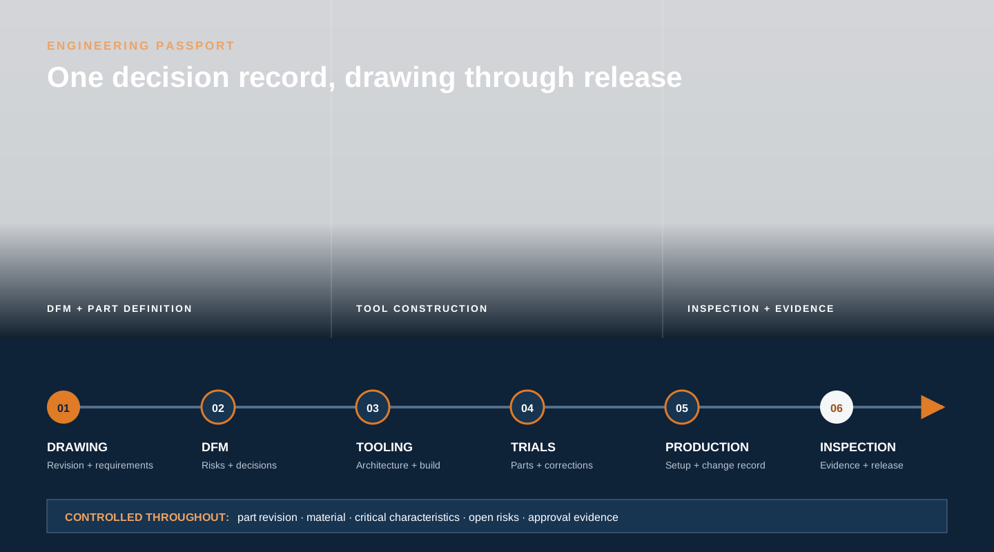
The mold cycle repeats in seconds or minutes; the manufacturing program develops across drawings, DFM decisions, tooling, trials, process approval, and inspection. Keeping those decisions connected makes changes and acceptance easier to review.
Resolve geometry before mold steel is cut
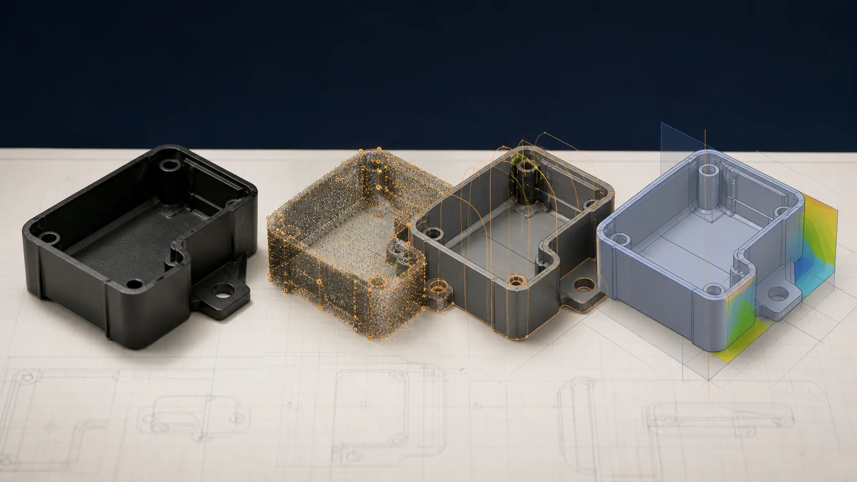
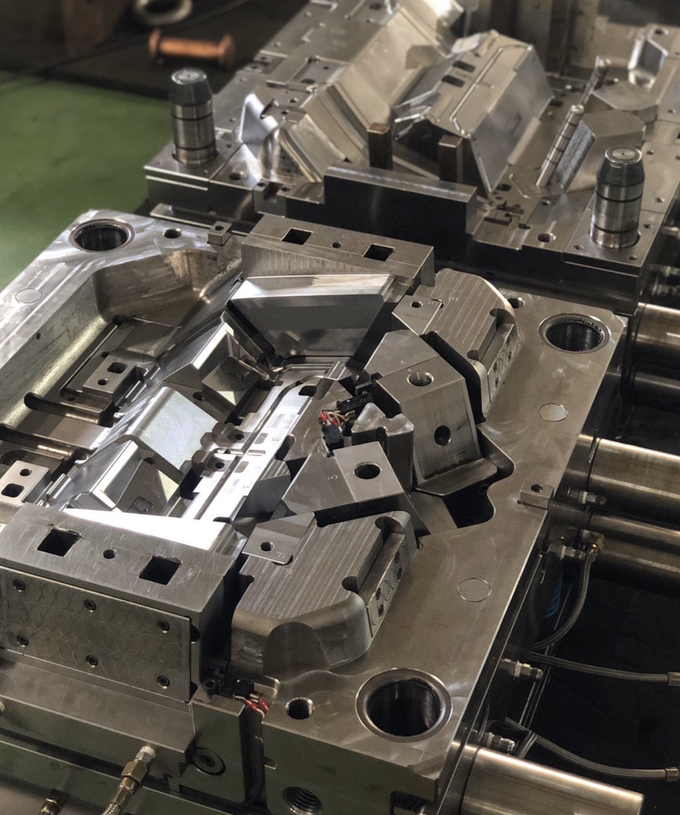
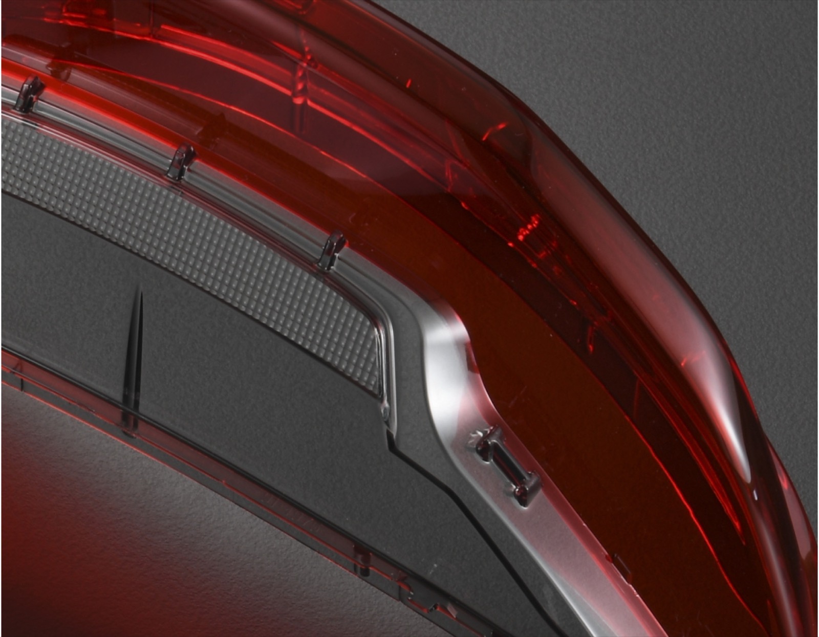
Design for manufacturability connects the CAD model to resin flow, cooling, mold opening, ejection, appearance, and inspection. The useful output is a record of decisions and open risks—not a generic checklist applied without context.
Wall sections and transitions
Review heavy sections, abrupt transitions, ribs, bosses, and coring together with the selected resin.
Draft and ejection
Confirm pull direction, surface finish, undercuts, side actions, and where ejection may mark or distort the part.
Gate, flow, and appearance
Connect gate position and flow direction to weld lines, pressure demand, orientation, and visible surfaces.
Cooling and dimensional control
Identify critical interfaces and acceptance requirements before cooling and inspection strategies are finalized.
Continue with the injection molding DFM guide for a focused pre-tooling review.
Select material from the part's operating requirements
A resin grade should be selected against the application rather than from a generic list of plastics. Reinforcement, colorant, additives, moisture conditioning, recycled content, and substitution rules may also affect processing and acceptance.
| Design question | Why it matters | Evidence to provide |
|---|---|---|
| What loads and interfaces control? | Strength, stiffness, impact, fatigue, creep, and assembly can point to different grades. | Load cases, mating parts, and service-life expectations |
| What environment will the part see? | Temperature, moisture, UV, and chemicals can affect performance and dimensions. | Exposure conditions and applicable tests |
| What must it look and feel like? | Color, gloss, texture, transparency, and touch influence resin and tool finish. | Color target, finish standard, cosmetic zones, and sample |
| Which records are required? | Customer and market requirements may constrain grade, traceability, testing, or change control. | Material specification and approval criteria |
Decision 04 · Acceptance
Define quality evidence before production release
Terms such as “high precision” do not define acceptance. Use the controlled drawing, datum scheme, critical dimensions, material specification, cosmetic standard, functional tests, inspection methods, and required submission format.
- Dimensions: identify features affecting fit, sealing, alignment, or function.
- Appearance: define viewing surfaces, texture, color, and allowable conditions.
- Material: name the approved grade or the requirements it must satisfy.
- Evidence: state which dimensional, material, capability, or customer records are required.
Review dimensional planning, mold trials, and first article inspection for the next level of detail.
Choose the molding route that matches the geometry
| Project signal | Relevant route | Question to resolve |
|---|---|---|
| One resin and a repeatable production part | Custom injection molding | Does expected demand support dedicated tooling? |
| Two materials or colors in one component | Two-shot (2K) molding | Are the materials compatible and the interface designed for bonding? |
| Metal hardware or a second substrate | Insert molding or overmolding | How will the insert be located, retained, and loaded? |
| Geometry still needs manufacturability review | DFM and tooling review | Which risks should close before tooling commitment? |
Prepare the engineering handoff
Bring controlled inputs, not only a request for price
Share what is known and identify what remains open. A useful review begins with the current model and drawing, material requirements, expected demand, critical interfaces, appearance, and required validation evidence.