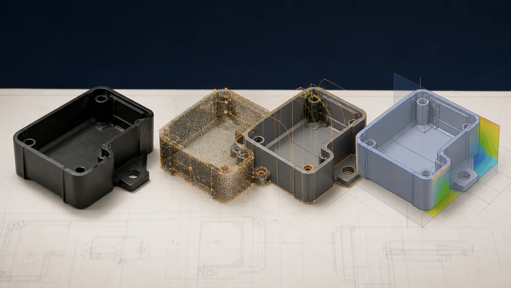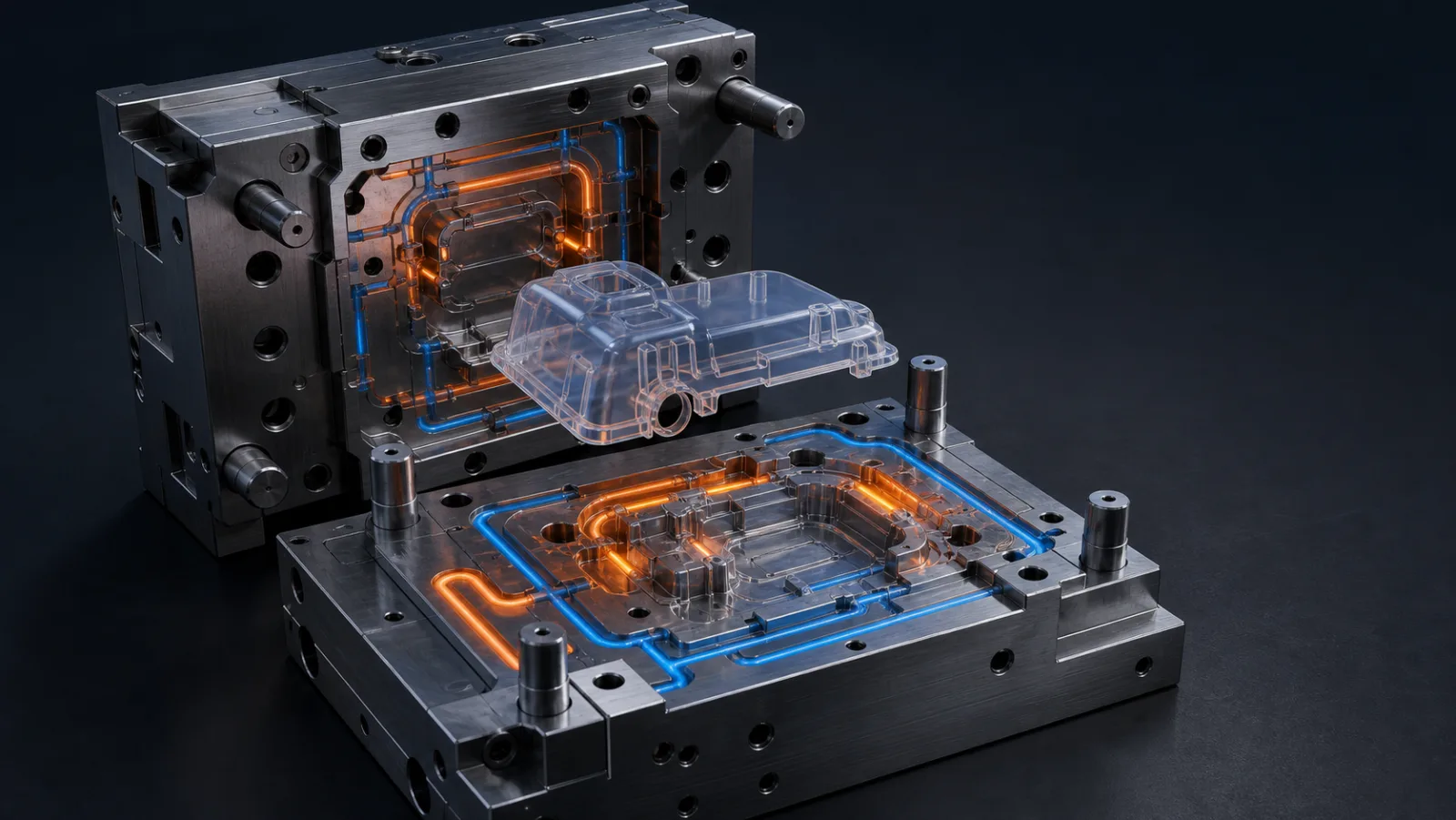
What matters most
- Use part thickness, resin, runner, cavity count, mold material, and target process conditions as inputs.
- Review channel distance, spacing, circuits, baffles, bubblers, inserts, actions, and inaccessible regions.
- Plan flow direction, pressure loss, temperature monitoring, parallel circuits, and cavity-to-cavity consistency.
Design cooling around heat and geometry
Evaluate the technical choice together with part requirements, tooling consequences, production controls, and the evidence required for approval.
Heat load
Use part thickness, resin, runner, cavity count, mold material, and target process conditions as inputs.
Layout
Review channel distance, spacing, circuits, baffles, bubblers, inserts, actions, and inaccessible regions.
Balance
Plan flow direction, pressure loss, temperature monitoring, parallel circuits, and cavity-to-cavity consistency.
Maintenance
Provide connectors, cleaning access, corrosion control, leak checks, and circuit identification.
Technical guide
The sections below retain the detailed design, tooling, process, and quality context needed to evaluate this topic beyond the summary.
Key Takeaways
- 1 Cooling accounts for 60–70% of total injection molding cycle time — making it the single largest driver of production throughput, per-unit cost, and part quality.
- 2 Four cooling element types serve distinct geometries: straight channels (planar cores), baffles (corners and ribs), bubblers (deep cores), and conformal inserts (complex curved surfaces).
- 3 Conformal cooling produced via DMLS can reduce cycle time by 20–40%, with one documented case study dropping cycle time from 35 to 15 seconds — recovering tooling premium within two months on a 5-million-unit program.
- 4 Six parameters govern every cooling circuit: channel diameter (8–12 mm), wall distance (1.5–2.5× diameter), pitch (2–3× diameter), coolant velocity (1.5–3.0 m/s), Reynolds number (>10,000), and inlet-to-outlet ΔT (<5°C).
Most tooling decisions attract attention — gate location, cavity steel grade, runner system. Cooling rarely does. Yet the cooling circuit is the single component that determines how fast a mold can run, whether parts warp, and whether dimensional tolerances hold across a million-shot program. This guide explains the physics, the circuit element choices, the channel design rules, and the economics of upgrading to conformal cooling — so you can make tooling decisions that pay back over program life rather than just minimizing upfront cost.
Why Cooling Dominates the Injection Molding Cycle
An injection molding cycle has four stages: fill, pack, cooling, and ejection. Fill and pack combined typically last 2–5 seconds for most commodity parts. Ejection takes under a second. Cooling occupies everything in between — and according to Aprios Manufacturing and ZetarMold’s cooling design analysis, it accounts for 60–70% of total cycle time across most thermoplastic programs.
The reason is thermodynamic: plastic enters the cavity at melt temperature (200–320°C depending on resin), and must be extracted to below the material’s heat deflection temperature before ejection. Any residual heat at ejection causes deformation under ejector pin force, dimensional drift from continued crystallization, or surface blemishes from differential shrinkage. Non-uniform cooling introduces an additional failure mode — differential shrinkage across the part creates internal stress, which releases as warpage. According to PMC simulation research on conformal channels, conventional straight-drilled circuits produce peak-to-peak temperature variations of 5–7°C across the cavity surface; conformal cooling reduces that to 2–3°C, directly reducing warpage and sink marks without changing resin or process parameters.
The practical implication: a mold that cools unevenly costs more to run every shot, every day, for the life of the program. Optimizing the cooling circuit at the DFM stage is the highest-leverage tooling investment available.
The Four Cooling Circuit Element Types
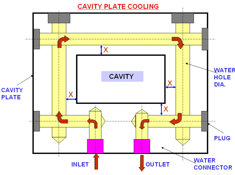
No single cooling element type suits every part geometry. Experienced mold engineers select among four configurations — often combining two or more in the same tool:
Straight-drilled channels are the standard configuration for most flat or gently curved cavity plates. Coolant enters one port, flows through a network of intersecting or parallel drilled holes, and exits at the outlet. They are low-cost, maintainable, and sufficient for parts with planar geometry and wall thickness below 3 mm. Their limitation is geometric: drill bits travel in straight lines and cannot follow a curved part surface.
Baffles redirect coolant flow into areas that straight channels cannot reach — particularly corners, ribs, and narrow cavity sections. A baffle is an insert placed inside a drilled channel that forces coolant to reverse direction, effectively doubling the contact length within a confined zone. They are essential for cores with width-to-depth ratios below 3:1 where a standard channel cannot maintain adequate flow velocity.
Bubblers are used in deep, narrow cores where baffles cannot be positioned. A small-diameter tube is inserted into a blind-drilled hole; coolant flows down the tube center and returns up the annular gap between tube and hole wall. They are the standard solution for cores deeper than 50 mm, ejector-free areas, and thin cores where any cross-drill would violate minimum wall requirements. The trade-off is flow resistance: bubblers require careful manifold design to avoid starving adjacent circuits.
Conformal cooling inserts are produced via metal additive manufacturing (DMLS or laser powder bed fusion using H13 or 1.2709 tool steel) and route channels at a constant distance from the cavity surface regardless of part geometry. They are the highest-cost option and the highest-performance option for complex curved surfaces, thick-wall sections, and high-volume programs where cycle time reduction translates directly to per-unit cost savings.
Channel Design Rules: Six Parameters That Govern Every Cooling Circuit
Correct channel geometry is the foundation of effective cooling. According to published research on cooling channel geometry effects and industry design references, six parameters govern performance:
| Parameter | Recommended Range | Effect of Violation |
|---|---|---|
| Channel diameter | 8–12 mm (10 mm typical) | Undersized → high flow resistance; oversized → laminar flow, poor heat transfer |
| Wall distance (channel centerline to cavity surface) | 1.5–2.5× channel diameter | Too close → stress risers, cracking risk; too far → poor heat extraction |
| Channel pitch (centerline to centerline) | 2–3× channel diameter | Too wide → hot spots between channels; too narrow → structural weakness |
| Coolant velocity | 1.5–3.0 m/s | Below 1.5 m/s → laminar flow, reduced heat transfer coefficient |
| Reynolds number | >10,000 (turbulent flow target) | Laminar flow (Re <2,300) reduces heat transfer by up to 50% vs. turbulent |
| Inlet-to-outlet ΔT | <5°C | ΔT >5°C creates temperature gradients that drive differential shrinkage and warpage |
These rules apply to both straight-drilled conventional circuits and conformal cooling layouts. The critical difference with conformal cooling is that channels can be placed at a uniform wall distance across a complex curved surface — something a drill bit cannot achieve.
Conventional vs. Conformal Cooling: A Performance Comparison
Xometry’s comparison analysis and Moldex3D simulation studies consistently show that conformal cooling outperforms conventional circuits on complex geometries, while conventional cooling remains the appropriate choice for flat or simple parts where straight channels can be positioned close to the cavity surface.
| Factor | Conventional (Straight-Drilled) | Conformal (DMLS Insert) |
|---|---|---|
| Cycle time reduction | Baseline | 20–40% reduction; up to 50% on optimized high-volume tools |
| Cavity temperature variation (ΔT) | 5–7°C | 2–3°C |
| Warpage (complex curved parts) | Higher; may require process compensation | Significantly reduced through uniform extraction |
| Tooling cost premium | Baseline | +20–30% on affected inserts |
| Suitable geometry | Flat plates, simple cores, shallow cavities | Curved surfaces, thick walls, undercuts, deep cores |
| Maintenance | Standard plugs and O-rings; easy field repair | Requires clean coolant; scale buildup is critical risk |
| Recommended volume threshold | Any volume | >500,000 shots or where warpage drives scrap cost |
When to Invest in Conformal Cooling: The ROI Calculation
Conformal cooling via DMLS carries a real cost premium — typically 20–30% on the affected mold inserts. Whether that premium pays back depends on three variables: production volume, current cycle time, and machine hourly rate.
A documented case study published by RJC Mold illustrates the economics clearly: a cosmetic PET housing running a 35-second cycle was converted to conformal cooling, dropping cycle time to 15 seconds — a 57% improvement in throughput. Tooling cost increased 30%. On a 5-million-unit order, the cycle time saving recovered the tooling premium within two months of production, with every subsequent month representing pure per-unit cost reduction.
According to SyBridge Technologies’ conformal cooling data, productivity improvements of 50% or more are achievable on thick-walled or geometrically complex parts. For thin-wall commodity parts with well-positioned conventional channels, the improvement is smaller — typically 10–15% — and may not justify the tooling premium at volumes below 500,000 shots.
The practical decision rule: if your current cycle time exceeds 20 seconds, the part has wall thickness above 2.5 mm or complex curved surfaces, and program volume exceeds 500,000 units per year, the ROI calculation almost always favors conformal cooling. LongTeam’s DFM review process evaluates cooling circuit feasibility as part of the initial tooling quotation — so the comparison is available before tooling commitment, not after.
Discuss Your Mold Cooling Design With LongTeam
LongTeam reviews cooling-circuit requirements as part of tooling DFM. Channel placement, cooling elements, and any conformal-cooling analysis are scoped to the program’s production volume and cycle-time targets. Contact us before cutting steel.
Contact LongTeam for DFM ReviewWhat to confirm before supplier review
Use the drawing, material specification, expected demand, application conditions, and acceptance requirements to turn a general process discussion into a program-specific review.
- Which regions are expected to cool slowly or unevenly?
- How will each circuit's flow and temperature be checked?
- Do actions or inserts interrupt the cooling path?
- What maintenance and water-quality controls apply?
Continue the engineering review
Use the related guides and capability pages to connect this topic to part geometry, tooling, molding, and qualification decisions.