Decision 01 · Authority and purpose
Define why the digital model is being rebuilt
Reverse engineering is useful when controlled CAD is missing, a legacy supplier has closed, an existing component needs modification, or a physical prototype must become a production candidate. The required accuracy and deliverables depend on the intended use.
- Reproduce: retain the interfaces and behavior that still matter.
- Repair: restore intended geometry rather than copying damage or wear.
- Modify: document requested changes and what must remain compatible.
- Re-tool: prepare the reconstructed definition for molding and inspection.
Start with sample condition and functional intent
A sample contains its original design plus manufacturing variation, service load, wear, environmental aging, repairs, and possible damage. Record those conditions before treating any measured surface as design intent.
| Sample observation | Risk if copied directly | Decision needed |
|---|---|---|
| Wear at a mating surface | The rebuilt part may preserve a loose or shifted interface | Restore the intended fit or retain the service adjustment? |
| Warped panel or flange | The CAD may reproduce distortion rather than nominal shape | Which datums and assembly conditions define nominal geometry? |
| Cracked clip or repaired feature | A known failure mode may be rebuilt into the new design | Should the feature be restored, strengthened, or redesigned? |
| Unknown production variation | One sample may not represent the original population | Are additional samples or mating parts needed? |
Decision 02 · Reconstruction
Move from captured geometry to controlled CAD
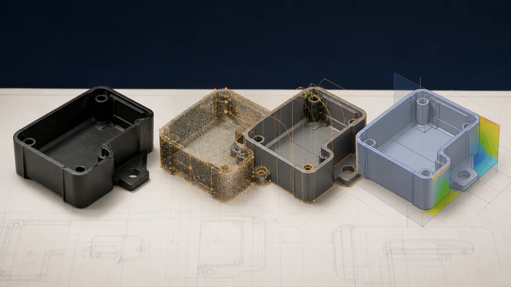
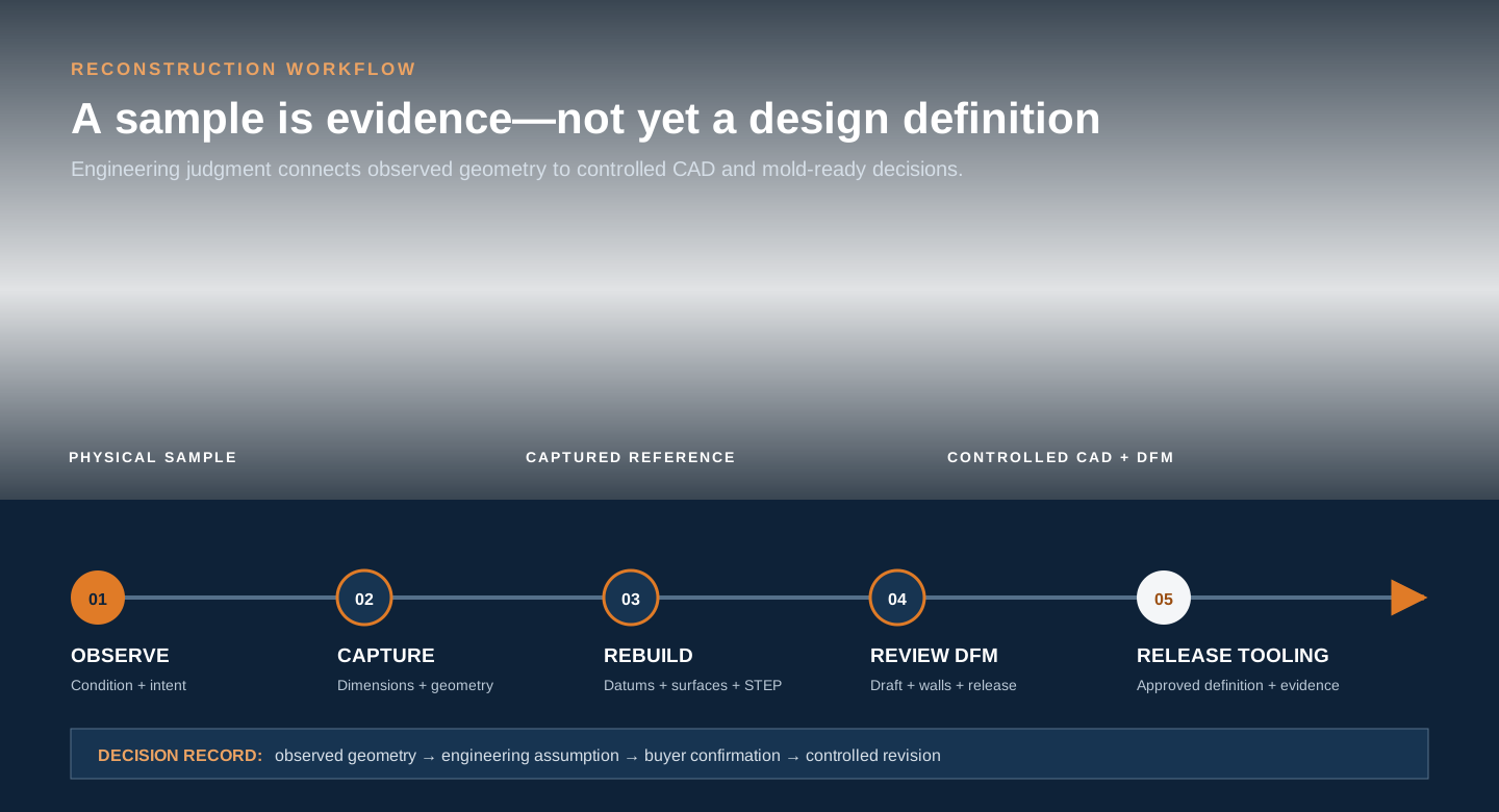
Measurement or scanning provides reference geometry. The engineer still needs to establish datums, recognize intended primitives and surfaces, rebuild features, close gaps, create a valid solid, and record assumptions before exporting a controlled STEP file.
| Reference approach | Useful for | Typical output | Limitation to manage |
|---|---|---|---|
| Direct dimensional measurement | Prismatic features, datums, holes, distances, and accessible interfaces | Controlled dimensions and construction geometry | Complex freeform surfaces and hidden features may need other evidence |
| Surface or point capture | Curved forms, textures, broad surfaces, and comparison | Point cloud or polygon mesh | The mesh is not automatically an editable design-intent model |
| Hybrid reconstruction | Parts combining functional dimensions with complex surfaces | Reference data plus rebuilt parametric or surface CAD | Requires explicit decisions where reference sources disagree |
Official workflows from Autodesk and SOLIDWORKS make the same distinction: captured data supports reconstruction but does not automatically become clean, editable CAD.
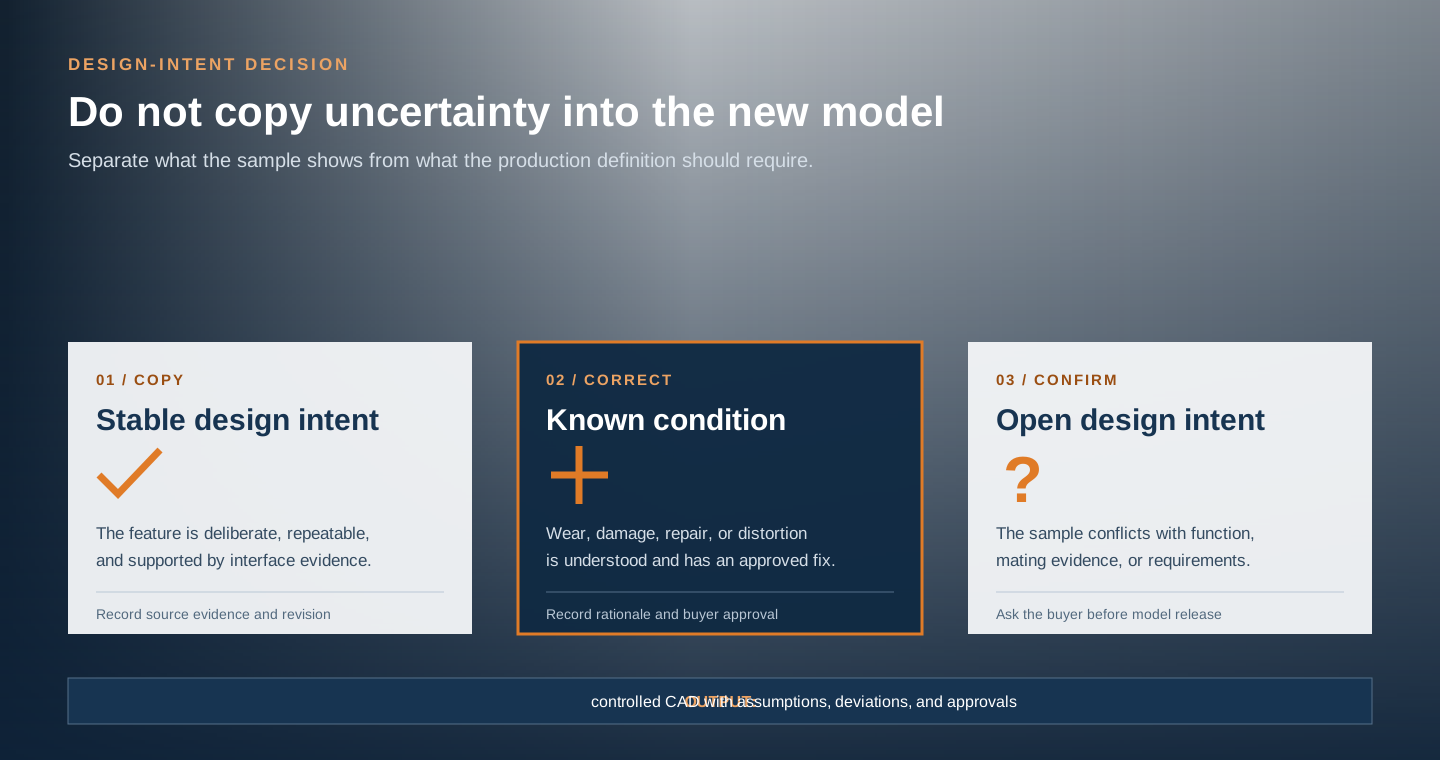
Choose what to copy, correct, or confirm
A defensible reconstruction separates observed geometry from approved design intent. Each meaningful feature should be classified before the CAD model is released.
Decision 03 · Verification
Match measurement evidence to the approval decision
No measurement is exact. Access, fixturing, surface condition, temperature, method, sample variation, and the characteristic being evaluated can affect the result. Define critical features and an acceptance method instead of applying one arbitrary tolerance to every surface.
- Which dimensions control fit, sealing, alignment, load, or appearance?
- Which datum scheme represents the surrounding assembly?
- Is one sample representative, or are several required to understand variation?
- Which features cannot be observed directly without additional evidence?
- Which comparison, inspection, or functional result approves the reconstructed model?
NIST dimensional-measurement guidance explains why measurement capability, manufacturing variation, and part tolerance must be considered together.
Prepare the reconstructed model for injection molding
A geometrically faithful STEP file is not automatically mold-ready. Review the reconstructed part for draft, wall thickness, pull direction, parting line, undercuts, material and shrinkage strategy, gates, venting, cooling, ejection, visible surfaces, and inspection.
Geometry and release
Confirm draft, undercuts, shutoffs, side actions, and which surfaces may move when manufacturability changes are applied.
Material and dimensions
Select the intended production grade before final shrinkage and critical dimensions are approved.
Flow and appearance
Connect gate, venting, weld-line, texture, and cosmetic requirements to the mold concept.
Inspection and change control
Translate critical interfaces into a drawing, datum structure, acceptance method, and controlled revision.
Continue with the injection molding DFM guide before tooling approval.
Decision 04 · Deliverables
Agree on the digital and approval package
| Deliverable | Purpose | What to agree |
|---|---|---|
| Native editable CAD | Controls features, surfaces, and future changes | Software/version, ownership, and included design history |
| STEP file | Provides a neutral solid for exchange and tooling review | Units, orientation, coordinate system, and revision |
| Controlled 2D drawing | Defines datums, dimensions, tolerances, notes, and acceptance | Critical characteristics and applicable standards |
| Assumption and deviation record | Separates observed geometry from approved corrections | Open questions, owner, disposition, and approval date |
| Comparison and DFM evidence | Shows model-to-sample review and mold-readiness decisions | Method, critical areas, limitations, and acceptance authority |
LongTeam can begin from controlled CAD or from a physical plastic part. The sample condition, critical dimensions, intended changes, reconstruction scope, and deliverables are confirmed for each program before connecting the model to mold design and tooling.